Circuits - MCAT Physical
Card 0 of 434
Two parallel plate capacitors C1 and C2 are arranged in parallel within a 10V circuit. If C1 stores 2C of charge and C2 stores 5C of charge, each over 3 seconds, what is the total capacitance of the circuit?
Two parallel plate capacitors C1 and C2 are arranged in parallel within a 10V circuit. If C1 stores 2C of charge and C2 stores 5C of charge, each over 3 seconds, what is the total capacitance of the circuit?
The capacitance of any capacitor can be calculated with the formula

Since the capacitors are arranged in parallel, the voltage drop across each will be equal, and in this case 10V. Adding capacitors in parallel is the same as adding resistors in series, where the total capacitance of the circuit is equal to the sum of all individual capacitors.


The capacitance of any capacitor can be calculated with the formula
Since the capacitors are arranged in parallel, the voltage drop across each will be equal, and in this case 10V. Adding capacitors in parallel is the same as adding resistors in series, where the total capacitance of the circuit is equal to the sum of all individual capacitors.
Compare your answer with the correct one above
Capacitors with capacitances of 3 μF, 7 μF and 10 μF are wired in parallel. What is the capacitance of the circuit?
- it cannot be determined without knowing the resistance of the circuit
- it cannot be determined without knowing the time constant in the circuit
- 20 μF
- approximately 1.75 μF
- none of these is correct
Response 3 is the correct choice. Electrons will space themselves as far apart as possible, because of charge repulsion; therefore, in a parallel arrangement, they will jump onto each capacitor and “load it up.” The parallel capacitance is calculated by simply adding the individual values. The value would be about 1.75 μF if the three were connected in series, where the formula is  (reciprocal of total equals sum of reciprocal of each). The time constant of a circuit is given by the formula τ = RC, and it relates to how fast a capacitor can charge to full capacitance.
Response 3 is the correct choice. Electrons will space themselves as far apart as possible, because of charge repulsion; therefore, in a parallel arrangement, they will jump onto each capacitor and “load it up.” The parallel capacitance is calculated by simply adding the individual values. The value would be about 1.75 μF if the three were connected in series, where the formula is
Compare your answer with the correct one above
A  and
and  capacitor are connected in series with a 12V battery. What is the maximum charge stored on the
  capacitor?
A
First find the equivalent capacitance of the two capacitors by adding their inverses.


Then, we can find the charge stored on this equivalent capacitor.

For capacitors in series the charges on each must be equal, and also equal to the charge on the equivalent capacitor. The answer is  .
.
First find the equivalent capacitance of the two capacitors by adding their inverses.
Then, we can find the charge stored on this equivalent capacitor.
For capacitors in series the charges on each must be equal, and also equal to the charge on the equivalent capacitor. The answer is
Compare your answer with the correct one above
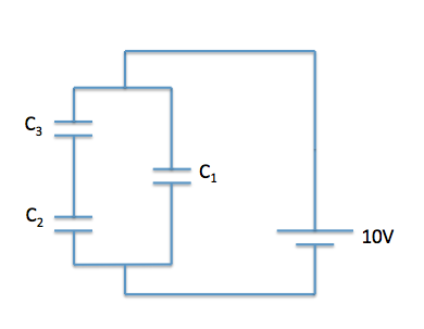
Batteries and AC current are often used to charge a capacitor. A common example of capacitor use is in computer hard drives, where capacitors are charged in a specific pattern to code information. A simplified circuit with capacitors can be seen below. The capacitance of C1 is 0.5 μF and the capacitances of C2 and C3 are 1 μF each. A 10 V battery with an internal resistance of 1 Ω supplies the circuit.
How is the charge stored on the capacitor?
Charge is evenly distributed on the surface of the capacitor. If we think back to electric force, we know that positive charges repel other positive charges and negative charges repel other negative charges; thus, the charges are evenly distributed to minimize the force between them. We can see how this looks in diagrammatic form below.
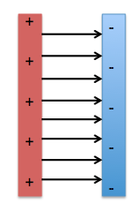
Charge is evenly distributed on the surface of the capacitor. If we think back to electric force, we know that positive charges repel other positive charges and negative charges repel other negative charges; thus, the charges are evenly distributed to minimize the force between them. We can see how this looks in diagrammatic form below.
Compare your answer with the correct one above
Batteries and AC current are often used to charge a capacitor. A common example of capacitor use is in computer hard drives, where capacitors are charged in a specific pattern to code information. A simplified circuit with capacitors can be seen below. The capacitance of C1 is 0.5 μF and the capacitances of C2 and C3 are 1 μF each. A 10 V battery with an internal resistance of 1 Ω supplies the circuit.
While the capacitor is charging, does the capacitor generate a magnetic field?
This question asks us to consider electromagnetism and what happens when a capacitor is charging. When a capacitor is charging, charge is accumulating on the surface over a period of time. Given that the electric field due to a capacitor is given by the formula E = σ/ε0, where σ is the charge per unit area and ε0 is the constant of permeability of free space, we can see that E is directly proportional to σ; therefore, the more charge that builds up, the higher the resulting E field.
Because σ is changing during charging, and thus E is changing, we also know that a magnetic field, B, must be created.
Remember the principle—a changing electric field induces a changing magnetic field, and a changing magnetic field induces a changing electric field.
Compare your answer with the correct one above
Batteries and AC current are often used to charge a capacitor. A common example of capacitor use is in computer hard drives, where capacitors are charged in a specific pattern to code information. A simplified circuit with capacitors can be seen below. The capacitance of C1 is 0.5 μF and the capacitances of C2 and C3 are 1 μF each. A 10 V battery with an internal resistance of 1 Ω supplies the circuit.
What is the equivalent capacitance of C2 and C3?
First, we need to determine how these capacitors are being added. We can see that they are being added in in series. Remember that capacitors in series are added as reciprocals:

Ceq = 0.5μF
First, we need to determine how these capacitors are being added. We can see that they are being added in in series. Remember that capacitors in series are added as reciprocals:
Ceq = 0.5μF
Compare your answer with the correct one above
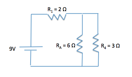
During the cold winter months, some gloves have the ability to provide extra warmth due to an internal heating source. A simplified circuit, similar to those in electric gloves, is comprised of a 9 V battery with no internal resistance and three resistors as shown in the image below.
What direction do electrons flow through the circuit?
Remember that convention dictates that current flows in the direction of positive charge (protons), thus, electrons flow in the opposite direction. Also remember that the larger length on the battery symbol on the circuit diagram indicates that current flows in this direction. In the diagram below, we can see that current flows clockwise, thus electrons flow counterclockwise.

Remember that convention dictates that current flows in the direction of positive charge (protons), thus, electrons flow in the opposite direction. Also remember that the larger length on the battery symbol on the circuit diagram indicates that current flows in this direction. In the diagram below, we can see that current flows clockwise, thus electrons flow counterclockwise.
Compare your answer with the correct one above
Batteries and AC current are often used to charge a capacitor. A common example of capacitor use is in computer hard drives, where capacitors are charged in a specific pattern to code information. A simplified circuit with capacitors can be seen below. The capacitance of C1 is 0.5 μF and the capacitances of C2 and C3 are 1 μF each. A 10 V battery with an internal resistance of 1 Ω supplies the circuit.
What is the equivalent capacitance of the circuit?
First, we need to determine how capacitors C2 and C3 are being added. We can see that they are being added in in series. Remember that capacitors in series are added as reciprocals.

C23 = 0.5μF
Next, we need to determine how we can find the Ceq by simplifying C23 and C1. We can see that Ceq and C1 are in parallel, thus we can directly add the individual capacitances.
Ceq = C23 + C1 = 0.5μF + 0.5μF = 1μF
First, we need to determine how capacitors C2 and C3 are being added. We can see that they are being added in in series. Remember that capacitors in series are added as reciprocals.
C23 = 0.5μF
Next, we need to determine how we can find the Ceq by simplifying C23 and C1. We can see that Ceq and C1 are in parallel, thus we can directly add the individual capacitances.
Ceq = C23 + C1 = 0.5μF + 0.5μF = 1μF
Compare your answer with the correct one above
Batteries and AC current are often used to charge a capacitor. A common example of capacitor use is in computer hard drives, where capacitors are charged in a specific pattern to code information. A simplified circuit with capacitors can be seen below. The capacitance of C1 is 0.5 μF and the capacitances of C2 and C3 are 1 μF each. A 10 V battery with an internal resistance of 1 Ω supplies the circuit.
How much total charge is stored by the capacitors of the circuit?
We are asked how much charge is stored in total on the circuit. We can use the equivalent capacitance and the voltage supplied by the battery to calculate the charge. Remember that Q = CV, where Q is the total charge, C is the equivalent capacitance, and V is the voltage. We must first solve for equivalent capacitance.
C2 and C3 are capacitors in series, while C1 is in parallel.

C23 = 0.5μF
Ceq = C23 + C1 = 0.5μF + 0.5μF = 1μF
Now we can plug in the Ceq and battery voltage to find the charge.
Q = (1μF)(10V) = 10μC
We are asked how much charge is stored in total on the circuit. We can use the equivalent capacitance and the voltage supplied by the battery to calculate the charge. Remember that Q = CV, where Q is the total charge, C is the equivalent capacitance, and V is the voltage. We must first solve for equivalent capacitance.
C2 and C3 are capacitors in series, while C1 is in parallel.
C23 = 0.5μF
Ceq = C23 + C1 = 0.5μF + 0.5μF = 1μF
Now we can plug in the Ceq and battery voltage to find the charge.
Q = (1μF)(10V) = 10μC
Compare your answer with the correct one above
Batteries and AC current are often used to charge a capacitor. A common example of capacitor use is in computer hard drives, where capacitors are charged in a specific pattern to code information. A simplified circuit with capacitors can be seen below. The capacitance of C1 is 0.5 μF and the capacitances of C2 and C3 are 1 μF each. A 10 V battery with an internal resistance of 1 Ω supplies the circuit.
How long does it take to fully charge the capacitors of the circuit?
In order to determine the time, we need to know the total charge stored on the capacitors. Remember that Q = CV, where Q is the total charge, C is the equivalent capacitance, and V is the voltage. We must first find the equivalent capacitance.
C2 and C3 are capacitors in series, while C1 is in parallel.

C23 = 0.5μF
Ceq = C23 + C1 = 0.5μF + 0.5μF = 1μF
Now we can plug in the Ceq and battery voltage to find the charge.
Q = (1μF)(10V) = 10μC
Additionally, we need to know the current the battery can provide (the charge per unit time). Knowing both the total charge and current will allow us to calculate the time. We can use V = IR to determine the current.
I = V/R = 10V/1Ω = 10A = 10C/sec
We can equate charge and current to determine time.
10μC = 10 C/t
t = 10 C/10 μC = 1 * 106s or 11.6days
In order to determine the time, we need to know the total charge stored on the capacitors. Remember that Q = CV, where Q is the total charge, C is the equivalent capacitance, and V is the voltage. We must first find the equivalent capacitance.
C2 and C3 are capacitors in series, while C1 is in parallel.
C23 = 0.5μF
Ceq = C23 + C1 = 0.5μF + 0.5μF = 1μF
Now we can plug in the Ceq and battery voltage to find the charge.
Q = (1μF)(10V) = 10μC
Additionally, we need to know the current the battery can provide (the charge per unit time). Knowing both the total charge and current will allow us to calculate the time. We can use V = IR to determine the current.
I = V/R = 10V/1Ω = 10A = 10C/sec
We can equate charge and current to determine time.
10μC = 10 C/t
t = 10 C/10 μC = 1 * 106s or 11.6days
Compare your answer with the correct one above
Batteries and AC current are often used to charge a capacitor. A common example of capacitor use is in computer hard drives, where capacitors are charged in a specific pattern to code information. A simplified circuit with capacitors can be seen below. The capacitance of C1 is  and the capacitances of C2 and C3 are
  each. A
  battery with an internal resistance of
  supplies the circuit.
How much potential energy is stored by the capacitors of the circuit?
Batteries and AC current are often used to charge a capacitor. A common example of capacitor use is in computer hard drives, where capacitors are charged in a specific pattern to code information. A simplified circuit with capacitors can be seen below. The capacitance of C1 is
How much potential energy is stored by the capacitors of the circuit?
First, we need to determine the type of energy being stored by the capacitors in the circuit. As this is an electric circuit, electric energy is being stored. Thus, we can use the formula for potential energy stored in a capacitor, U = ½CV2. We must first find the equivalent capacitance.
C2 and C3 are capacitors in series, while C1 is in parallel.

C23 = 0.5μF
Ceq = C23 + C1 = 0.5μF + 0.5μF = 1μF
U = ½CV2 = ½(1μF)(10V)2 = 5 * 10-5J
First, we need to determine the type of energy being stored by the capacitors in the circuit. As this is an electric circuit, electric energy is being stored. Thus, we can use the formula for potential energy stored in a capacitor, U = ½CV2. We must first find the equivalent capacitance.
C2 and C3 are capacitors in series, while C1 is in parallel.
C23 = 0.5μF
Ceq = C23 + C1 = 0.5μF + 0.5μF = 1μF
U = ½CV2 = ½(1μF)(10V)2 = 5 * 10-5J
Compare your answer with the correct one above
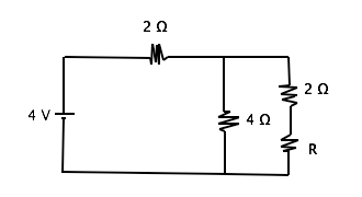
What is the change in electrical potential energy for a charge of -2 µC moving through the circuit shown above?

What is the change in electrical potential energy for a charge of -2 µC moving through the circuit shown above?
Given that
V(q) = U
When V is voltage, U is electrical potential energy and q is charge, we can solve by plugging in 4 for V and -2 for q. Also, we must understand that the electric potential energy of a particle decreases as it moves from an area of higher energy to one of lower energy. For an electron, it has higher energy in the negative terminal of the battery than it does in when getting to the positive terminal.
Compare your answer with the correct one above
Batteries and AC current are often used to charge a capacitor. A common example of capacitor use is in computer hard drives, where capacitors are charged in a specific pattern to code information. A simplified circuit with capacitors can be seen below. The capacitance of C1 is 0.5 μF and the capacitances of C2 and C3 are 1 μF each. A 10 V battery with an internal resistance of 1 Ω supplies the circuit.
Instead of air, assume that we insert a dielectric material with a dielectric constant k between the capacitor plates. How would the total capacitance of the circuit change?
In this question, we are asked how the total charge stored on the surface of the capacitors would change if we inserted a dielectric between the parallel plates. As we can see in the equation for capacitance based on physical properties,  , where k is the dielectric constant (k = 1 for air; k > 1 for all dielectric materials), ε0 is the constant of the permeability of free space, A is the area of the plates, and d is the distance between the plates.
If we insert a dielectric material, k > 1, the value of C increases, thus the overall capacitance of the circuit increases.
In this question, we are asked how the total charge stored on the surface of the capacitors would change if we inserted a dielectric between the parallel plates. As we can see in the equation for capacitance based on physical properties,
If we insert a dielectric material, k > 1, the value of C increases, thus the overall capacitance of the circuit increases.
Compare your answer with the correct one above
Batteries and AC current are often used to charge a capacitor. A common example of capacitor use is in computer hard drives, where capacitors are charged in a specific pattern to code information. A simplified circuit with capacitors can be seen below. The capacitance of C1 is 0.5 μF and the capacitances of C2 and C3 are 1 μF each. A 10 V battery with an internal resistance of 1 Ω supplies the circuit.
Capacitors in series share the same __________, while capacitors in parallel share the same __________.
As with resistors, capacitors in series share the same current. This is a re-statement of the law of conservation of charge. In contrast, capacitors and resistors in parallel share the same voltage.
As with resistors, capacitors in series share the same current. This is a re-statement of the law of conservation of charge. In contrast, capacitors and resistors in parallel share the same voltage.
Compare your answer with the correct one above
Two capacitors are fully charged and connected in series in a circuit powered by a  battery. Find the charge stored.


Two capacitors are fully charged and connected in series in a circuit powered by a
First, we need to find the equivalent capacitance for the capacitors in series.


Now we can find the charge using the equation  .
.
(1.5F) = 15C")
First, we need to find the equivalent capacitance for the capacitors in series.
Now we can find the charge using the equation
Compare your answer with the correct one above
Which of the following statements about dielectrics is false?
Which of the following statements about dielectrics is false?
Dielectrics are put between two parallel plates of a capacitor to increase capacitance. This is done by holding voltage constant and increasing charge, or decreasing voltage and holding charge constant.
This can be understood using the equation  . Either an increase in charge or a decrease in voltage will increase the capacitance.
Dielectrics are put between two parallel plates of a capacitor to increase capacitance. This is done by holding voltage constant and increasing charge, or decreasing voltage and holding charge constant.
This can be understood using the equation
Compare your answer with the correct one above
Which of the following arrangements of parallel conducting plates would store the most charge when connected in series with a battery of voltage  ?
?
Assume that in each arrangement, each plate has area  .
.
Which of the following arrangements of parallel conducting plates would store the most charge when connected in series with a battery of voltage
Assume that in each arrangement, each plate has area
Relevant equations:


The first equation shows that charge  is directly proportional to capacitance
  , so we want to maximize
  in order to find the maximum charge.
The second equation shows that  is directly proportional to the dielectric constant
  , and inversely proportional to distance
  . To increase capacitance, we need
  to be large and
  to be small.
A smaller distance ") and a larger dielectric constant (choosing glass instead of air) will lead to a large stored charge.
and a larger dielectric constant (choosing glass instead of air) will lead to a large stored charge.
Relevant equations:
The first equation shows that charge
The second equation shows that
A smaller distance
Compare your answer with the correct one above
An RC circuit is assembled by connecting a voltage source, a resistor, and a capacitor in series. The capacitor in the circuit has a potential difference of  . After discharging the capacitor for two seconds, the potential difference of the capacitor drops to
  . What are the approximate capacitance and time constant of this circuit if the resistor has a resistance of
  ?
?
An RC circuit is assembled by connecting a voltage source, a resistor, and a capacitor in series. The capacitor in the circuit has a potential difference of
To solve this question, we need to use the equation that describes voltage decay during capacitor discharging:

Here,  is the voltage after a certain amount of time,
  is the initial voltage,
  is the time elapsed,
  is the resistance of the resistor, and
  is the capacitance of the capacitor. We can rearrange this equation in such a way that we solve for capacitance,
  :
:
")
")
To remove the exponential  from the equation, we need to take the natural logarithm of both sides:
= \frac{-t}{RC}")
Solving for  gives us:


The time constant,  , of an RC circuit is the product of the resistance and the capacitance; therefore, the time constant of this circuit is:

To solve this question, we need to use the equation that describes voltage decay during capacitor discharging:
Here,
To remove the exponential
Solving for
The time constant,
Compare your answer with the correct one above
During discharge, the decay of voltage in a capacitor is an example of __________ decay, the decay of current in a capacitor is an example of __________ decay, and the decay of charge in a capacitor is an example of __________ decay.
During discharge, the decay of voltage in a capacitor is an example of __________ decay, the decay of current in a capacitor is an example of __________ decay, and the decay of charge in a capacitor is an example of __________ decay.
A capacitor is an electrical device consisting of two parallel conducting plates that store charge. A capacitor undergoes two processes: charging and discharging. During charging, a capacitor accumulates and stores charge between the two plates. During discharge, a capacitor loses the stored charge. Since there is a decrease in the amount of charge during discharge, there is also a decrease (or decay) in current and voltage in a discharging capacitor. The decay of all these parameters is characterized by the equation:

Here,  and
and  denote the variable (voltage, current, or charge),
  denotes the time elapsed,
  denotes the resistance of the resistor, and
  denotes the capacitance of the capacitor. This is an equation for exponential decay; therefore, all the variables undergo exponential decay in a discharging capacitor.
A capacitor is an electrical device consisting of two parallel conducting plates that store charge. A capacitor undergoes two processes: charging and discharging. During charging, a capacitor accumulates and stores charge between the two plates. During discharge, a capacitor loses the stored charge. Since there is a decrease in the amount of charge during discharge, there is also a decrease (or decay) in current and voltage in a discharging capacitor. The decay of all these parameters is characterized by the equation:
Here,
Compare your answer with the correct one above
A capacitor has a capacitance of  and is connected in series with a resistor to form an RC circuit. At
  , the capacitor has a potential difference of
  . At
. At  , the potential difference has dropped to
  .
.
What is the resistance of the resistor?
A capacitor has a capacitance of
What is the resistance of the resistor?
The question states that the potential difference dropped from  to
to  in
in  . The percentage of voltage drop is:

This means that there was a  voltage drop in
  . The definition of time constant is the time it takes for a capacitor to discharge to
  of its original value, or have a
  drop; therefore, the time constant for this circuit is .
The time constant, tau, for an RC circuit is the product of the resistance of the resistor and the capacitance of the capacitor:

We can use this equation to solve for the resistance of the resistor:

Solving for resistance gives us:


Notice that you could have used the voltage decay equation to solve this problem; however, knowing the definition of time constant simplifies the problem and reduces the amount of calculations.
The question states that the potential difference dropped from
This means that there was a
The time constant, tau, for an RC circuit is the product of the resistance of the resistor and the capacitance of the capacitor:
We can use this equation to solve for the resistance of the resistor:
Solving for resistance gives us:
Notice that you could have used the voltage decay equation to solve this problem; however, knowing the definition of time constant simplifies the problem and reduces the amount of calculations.
Compare your answer with the correct one above