Circuits
Help Questions
MCAT Physical › Circuits
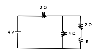
What is the resistance through resistor R given that the current through the circuit is 1 A?
2 Ω
1 Ω
0.5 Ω
4 Ω
Explanation
In order to solve this problem, we must understand that the resistance of parallel resistors is added inversely and that series resistors are added directly.
Series

Parallel
Ohm’s Law

We can first find the total resistance of the circuit to be 4 Ω using ohm's law . Then by subtracting the resistor in series (2 Ω) from the total resistance, we can set the remaining parallel resistors equal to 2 Ω. Finally, we can use the parallel resistor equation to find R. Remember that you can simply count the two resistors in series on the far right branch of the circuit (R and 2 Ω) as one number in the parallel resistor formula giving us
we can solve for this to find that R = 2 Ω
Capacitors with capacitances of 3 μF, 7 μF and 10 μF are wired in parallel. What is the capacitance of the circuit?
- it cannot be determined without knowing the resistance of the circuit
- it cannot be determined without knowing the time constant in the circuit
- 20 μF
- approximately 1.75 μF
- none of these is correct
3
1
2
4
5
Explanation
Response 3 is the correct choice. Electrons will space themselves as far apart as possible, because of charge repulsion; therefore, in a parallel arrangement, they will jump onto each capacitor and “load it up.” The parallel capacitance is calculated by simply adding the individual values. The value would be about 1.75 μF if the three were connected in series, where the formula is 
Capacitors with capacitances of 3 μF, 7 μF and 10 μF are wired in parallel. What is the capacitance of the circuit?
- it cannot be determined without knowing the resistance of the circuit
- it cannot be determined without knowing the time constant in the circuit
- 20 μF
- approximately 1.75 μF
- none of these is correct
3
1
2
4
5
Explanation
Response 3 is the correct choice. Electrons will space themselves as far apart as possible, because of charge repulsion; therefore, in a parallel arrangement, they will jump onto each capacitor and “load it up.” The parallel capacitance is calculated by simply adding the individual values. The value would be about 1.75 μF if the three were connected in series, where the formula is
What is the resistance through resistor R given that the current through the circuit is 1 A?
2 Ω
1 Ω
0.5 Ω
4 Ω
Explanation
In order to solve this problem, we must understand that the resistance of parallel resistors is added inversely and that series resistors are added directly.
Series
Parallel
Ohm’s Law
We can first find the total resistance of the circuit to be 4 Ω using ohm's law . Then by subtracting the resistor in series (2 Ω) from the total resistance, we can set the remaining parallel resistors equal to 2 Ω. Finally, we can use the parallel resistor equation to find R. Remember that you can simply count the two resistors in series on the far right branch of the circuit (R and 2 Ω) as one number in the parallel resistor formula giving us
we can solve for this to find that R = 2 Ω
A 


Explanation
Relevant equations:

When the circuit is first connected, the current increases from zero to its final value. During this time as the current changes, the inductor has a voltage across it. After a long period, the current has built up to its maximum value.
After a long period, 

Plugging in our values for voltage and resistance, we can solve for the final current.

Batteries and AC current are often used to charge a capacitor. A common example of capacitor use is in computer hard drives, where capacitors are charged in a specific pattern to code information. A simplified circuit with capacitors can be seen below. The capacitance of C1 is 0.5 μF and the capacitances of C2 and C3 are 1 μF each. A 10 V battery with an internal resistance of 1 Ω supplies the circuit.
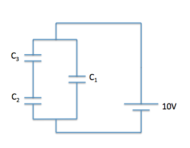

What is the equivalent capacitance of the circuit?
1μF
2μF
3μF
4μF
Explanation
First, we need to determine how capacitors C2 and C3 are being added. We can see that they are being added in in series. Remember that capacitors in series are added as reciprocals.

C23 = 0.5μF
Next, we need to determine how we can find the Ceq by simplifying C23 and C1. We can see that Ceq and C1 are in parallel, thus we can directly add the individual capacitances.
Ceq = C23 + C1 = 0.5μF + 0.5μF = 1μF
What is the change in electrical potential energy for a charge of -2 µC moving through the circuit shown above?
–8 µJ
–2 µJ
2 µJ
8 µJ
16 µJ
Explanation
Given that
V(q) = U
When V is voltage, U is electrical potential energy and q is charge, we can solve by plugging in 4 for V and -2 for q. Also, we must understand that the electric potential energy of a particle decreases as it moves from an area of higher energy to one of lower energy. For an electron, it has higher energy in the negative terminal of the battery than it does in when getting to the positive terminal.
Batteries and AC current are often used to charge a capacitor. A common example of capacitor use is in computer hard drives, where capacitors are charged in a specific pattern to code information. A simplified circuit with capacitors can be seen below. The capacitance of C1 is 0.5 μF and the capacitances of C2 and C3 are 1 μF each. A 10 V battery with an internal resistance of 1 Ω supplies the circuit.
What is the equivalent capacitance of the circuit?
1μF
2μF
3μF
4μF
Explanation
First, we need to determine how capacitors C2 and C3 are being added. We can see that they are being added in in series. Remember that capacitors in series are added as reciprocals.
C23 = 0.5μF
Next, we need to determine how we can find the Ceq by simplifying C23 and C1. We can see that Ceq and C1 are in parallel, thus we can directly add the individual capacitances.
Ceq = C23 + C1 = 0.5μF + 0.5μF = 1μF
Consider the following circuit:


Water has been spilt on the circuit, occasionally creating a short in the circuit. The short is represented by the switch, which is closed when the circuit is shorted. What is the difference in power loss through the circuit when the switch is closed compared to being open?


Explanation
We will need to calculate total equivalent resistance for each of the two scenarios to calculate power losses.
SCENARIO 1: Switch Closed
When the switch is closed, a resistance-free path is created. This effectively reduces the current flow through the parallel resistors to zero. Therefore, we have a much simpler circuit, consisting only of R1 and R5. Since they are in series, we can simply add them:

The expression for power is:

Substituting Ohm's law for current, we get:
V=\frac{V^2}{R}")
Plugging in our values, we get:
^2}{7\Omega} = 20.57 W")
SCENARIO 2: Switch Open
Now that we have resistors in parallel, it will take two steps to condense the circuit. For the parallel part, we get:


Now, since everything is in series in this equivalent circuit, we can simply add it all up:

Again using the formula for power, we get:
^2}{\frac{71}{8}\Omega} = 16.23 W")
Now we can calculate the difference between the two scenarios:

A
Explanation
Relevant equations:
When the circuit is first connected, the current increases from zero to its final value. During this time as the current changes, the inductor has a voltage across it. After a long period, the current has built up to its maximum value.
After a long period,
Plugging in our values for voltage and resistance, we can solve for the final current.