All questions
Question 1
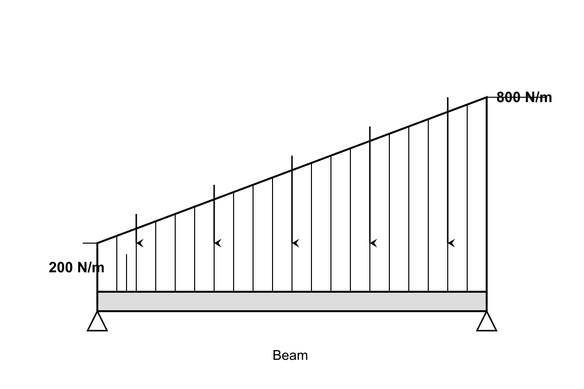
A distributed load is shown acting on a beam segment. Based on the load diagram provided, what is the correct interpretation of the load intensity at the right end compared to the left end?
- The load intensity increases linearly from 200 N/m to 800 N/m over the span (correct answer)
- The load intensity decreases linearly from 800 N/m to 200 N/m over the span
- The load intensity remains constant at 500 N/m throughout the entire span length
- The load intensity varies parabolically with maximum value of 800 N/m at midspan
- The load intensity increases exponentially from 200 N/m to 800 N/m over the span
Explanation: The trapezoidal load diagram shows the load intensity starting at 200 N/m on the left and increasing linearly to 800 N/m on the right, as indicated by the sloped top edge and numerical labels. Choice B reverses the direction. Choice C describes a uniform load. Choice D describes a parabolic variation not shown. Choice E describes exponential variation, but the straight sloped line indicates linear variation.
Question 2
Examine the free body diagram of joint C below. If the system is in equilibrium, which force component is incorrectly represented in this diagram?
- The horizontal component of member AC should be pointing in the opposite direction
- The vertical component of member BC should be pointing in the opposite direction (correct answer)
- The applied load P should be shown as a distributed force rather than concentrated
- Member AC should be shown in compression rather than tension based on the arrow direction
- The reaction at joint C should include a moment component for rotational equilibrium
Explanation: In the free body diagram, if member BC is in compression (pushing against the joint), the force should point away from the joint, not toward it. The vertical component direction shown suggests tension when the member geometry indicates compression. Choice A may be correct depending on the analysis method. Choice C is incorrect as concentrated loads are properly shown this way. Choice D confuses the sign convention. Choice E is wrong because joints in trusses don't carry moments.
Question 3
The loading diagram shows both point loads and distributed loads acting on a beam. Based on the representation, what is the total equivalent concentrated load that would produce the same resultant force as the distributed portion?
- The equivalent load is 12 kN acting at 2 m from the left support
- The equivalent load is 18 kN acting at 3 m from the left support (correct answer)
- The equivalent load is 15 kN acting at 2.5 m from the left support
- The equivalent load is 20 kN acting at 4 m from the left support
- The equivalent load is 24 kN acting at 3.5 m from the left support
Explanation: The distributed load varies linearly from 2 kN/m to 4 kN/m over 6 m length. The total load is the area of the trapezoid: (1/2)(2+4)(6) = 18 kN. The centroid of a trapezoid from the left end is at: (6/3)[(2×2+4)/(2+4)] = 3 m from the start of the distributed load. Choice A has wrong magnitude and location. Choice C has wrong magnitude. Choices D and E have wrong magnitudes and locations outside the distributed load region.
Question 4
Examine the influence line diagram shown for a specific structural response. The diagram exhibits both positive and negative ordinates. What structural response quantity does this influence line most likely represent?
- Reaction force at a support location, which can only have positive values
- Deflection at midspan of a simply supported beam under moving loads
- Bending moment at an interior point of a continuous beam system
- Axial force in a truss member that remains in tension under all loading
- Shear force in a beam that changes sign depending on load position (correct answer)
Explanation: An influence line with both positive and negative values indicates a response that can change sign based on load position. Shear force is the most common response exhibiting this behavior - positive when the load is on one side of the section, negative when on the other side. Choice A (reaction) is typically always positive. Choice B (deflection) is usually always negative for downward loads. Choice C (moment in continuous beam) can change sign but is less commonly shown. Choice D contradicts the given information about sign changes.
Question 5
Referring to the beam cross-section diagram provided, the dimension 'c' represents the distance from the neutral axis to the extreme fiber. For stress analysis purposes, how should this dimension be interpreted?
- The distance should be measured to the tension fiber only, regardless of loading direction
- The distance should be measured to the compression fiber only, regardless of loading direction
- The distance should be measured to whichever extreme fiber experiences the maximum stress magnitude (correct answer)
- The distance should always be measured to the top fiber since it represents the standard orientation
- The distance should be measured to the centroidal axis of the entire cross-sectional area
Explanation: The distance 'c' in flexure formula (σ = Mc/I) represents the distance to the extreme fiber where maximum stress occurs. For asymmetric sections, this may be either the top or bottom fiber, depending on which is farther from the neutral axis. Choices A and B are incorrect as both tension and compression fibers must be considered. Choice D assumes symmetric sections. Choice E is incorrect as 'c' measures to the extreme fiber, not back to the centroid.
Question 6
The deflection diagram shown represents the deformed shape of a loaded beam. Based on the curvature characteristics visible in this diagram, what can be inferred about the moment distribution?
- The moment is constant throughout the beam length since deflection increases uniformly
- The moment is zero at locations where the deflection curve has inflection points (correct answer)
- The moment is maximum at the location of maximum deflection in the beam span
- The moment changes sign at points where the curvature of the deflection curve changes
- The moment distribution cannot be determined from deflection information alone
Explanation: Inflection points in the deflection curve occur where curvature changes sign, which corresponds to locations where the bending moment is zero (since curvature is proportional to M/EI). Choice A is incorrect as uniform deflection increase doesn't indicate constant moment. Choice C confuses maximum deflection with maximum moment locations. Choice D describes inflection points, not general curvature changes. Choice E is incorrect since moment and curvature are directly related.
Question 7
The cross-sectional view provided shows a composite beam with two different materials. The interface between materials is marked with a dashed line. For stress analysis, why is this interface location critical?
- The interface represents the location where maximum bending stress will always occur
- The interface indicates where the beam is most likely to fail under loading
- The interface marks a discontinuity in material properties requiring special analysis consideration (correct answer)
- The interface shows where the neutral axis of the composite section is located
- The interface represents a construction joint that has no effect on structural behavior
Explanation: The interface between different materials creates a discontinuity in material properties (different E values), requiring transformed section analysis or compatibility considerations. Stress and strain distributions change across this boundary. Choice A is incorrect - maximum stress occurs at extreme fibers. Choice B may be true but isn't the primary analytical concern. Choice D confuses the interface with neutral axis location. Choice E ignores the significance of material property changes.
Question 8
The stress element shown in the figure represents the state of stress at a critical point in a structural member. Based on the stress values and orientations indicated, what type of stress state does this element represent?
- Pure shear stress state with no normal stress components acting on the element
- Uniaxial stress state with normal stress in one direction and zero shear stresses
- Biaxial stress state with normal stresses in two directions and zero shear stress
- General plane stress state with both normal and shear stress components present (correct answer)
- Hydrostatic stress state with equal normal stresses in all directions on the element
Explanation: The stress element shows normal stresses (σₓ = 80 MPa, σᵧ = 40 MPa) and shear stress (τₓᵧ = 25 MPa), which constitutes a general plane stress state. Choice A is incorrect due to presence of normal stresses. Choice B is wrong because stress exists in both x and y directions plus shear. Choice C ignores the shear stress component. Choice E requires equal normal stresses in all directions, which is not the case here.
Question 9
In the three-dimensional force system diagram provided, forces F₁, F₂, and F₃ act at point O with their direction cosines indicated. To achieve equilibrium, what constraint must be satisfied by these direction cosines?
- The sum of all direction cosines must equal zero for each coordinate direction
- Each individual force vector must have direction cosines that sum to unity
- The dot product of any two force vectors must equal zero for orthogonality
- The magnitude-weighted sum of direction cosines must be zero in each coordinate direction (correct answer)
- Direction cosines are independent of equilibrium requirements in three-dimensional systems
Explanation: For equilibrium in 3D, ΣFₓ = ΣFᵧ = ΣFᵧ = 0, which means Σ(Fᵢ × lᵢ) = 0, Σ(Fᵢ × mᵢ) = 0, Σ(Fᵢ × nᵢ) = 0, where Fᵢ is force magnitude and lᵢ, mᵢ, nᵢ are direction cosines. Choice A ignores force magnitudes. Choice B describes the property of direction cosines for unit vectors (l² + m² + n² = 1). Choice C describes orthogonal vectors, not equilibrium. Choice E is incorrect as direction cosines directly relate to equilibrium through force components.
Question 10
In the truss diagram shown, members are labeled with letters and joints with numbers. What is the most likely reason that member CD appears with a different line style (dashed) compared to the other members?
- Member CD is a zero-force member that carries no load under the given loading condition (correct answer)
- Member CD represents a cable element that can only resist tension forces effectively
- Member CD indicates a temporary construction member that will be removed after assembly
- Member CD shows a member with different material properties than the standard steel members
- Member CD represents a member that is not connected to the joints but floats freely
Explanation: Dashed lines in truss diagrams commonly indicate zero-force members - members that carry no internal force under the specific loading condition shown. This helps identify which members could potentially be removed without affecting structural stability under that loading. Choice B would typically be shown with a different symbol. Choice C relates to construction sequencing, not analysis. Choice D would be noted in a legend or specifications. Choice E would not be shown as a member at all.
Question 11
The force vector diagram shows three concurrent forces acting at point O. Based on the vector representation, what can be concluded about the equilibrium state of this system?
- The system is in equilibrium because the three force vectors form a closed triangle
- The system is not in equilibrium because the resultant vector has a magnitude of 150 N
- The system is in equilibrium only if the angles between vectors are exactly 120 degrees
- The system cannot be in equilibrium because concurrent forces require a fourth balancing force
Explanation: B
Question 12
In the structural diagram shown, the notation '2L/3' appears along member AB. What does this dimension most likely indicate in the context of structural analysis?
- The distance from point A to the location of maximum bending moment in the member
- The effective length of member AB for buckling analysis calculations in compression
- The horizontal distance from support A to the point where load P is applied (correct answer)
- The length of member AB measured along its centerline from joint A to joint B
- The tributary length of member AB that contributes to the total structural dead load
Explanation: The notation '2L/3' typically indicates a dimensional location along a span, most commonly where a load is applied. This represents the horizontal distance from support A to the load application point. Choice A refers to moment diagrams, not dimensional notation. Choice B relates to effective length factors (like K*L). Choice D would simply be labeled 'L' or the actual length. Choice E relates to load calculations, not geometric dimensions shown on diagrams.
Question 13
The moment diagram shown corresponds to a simply supported beam with specific loading. Based on the diagram characteristics, what can be concluded about the loading condition that produced this moment distribution?
- The beam carries a uniformly distributed load over its entire span length
- The beam carries two equal concentrated loads at the quarter points of the span
- The beam carries a single concentrated load at the midspan location only (correct answer)
- The beam carries a triangular distributed load with maximum intensity at midspan
- The beam carries concentrated loads at both ends with no intermediate loading
Explanation: The moment diagram shows a triangular distribution with maximum at midspan and zero at supports, which is characteristic of a single concentrated load at midspan of a simply supported beam. Choice A would produce a parabolic moment diagram. Choice B would show a trapezoidal shape with flat top between loads. Choice D would produce a more complex curved shape. Choice E would produce zero moment throughout (no loads create internal moments).
Question 14
In the beam diagram shown, what does the triangular symbol at point B most likely represent?
- A pin support that allows rotation but prevents translation in both directions (correct answer)
- A roller support that prevents vertical translation but allows horizontal movement
- A fixed support that prevents both rotation and translation in all directions
- A hinge connection that transfers moment but allows relative displacement
- A cable attachment point that can only resist tension forces in one direction
Explanation: The triangular symbol typically represents a pin support (also called a pinned or hinged support) that prevents translation in both x and y directions but allows rotation. Choice B describes a roller support (usually shown with wheels or rollers). Choice C describes a fixed support (shown with hatching or cross-hatching). Choice D incorrectly suggests hinges transfer moments (they don't). Choice E describes a cable or link, not represented by a triangular symbol.
Question 15
In the connection detail shown, the bolt pattern consists of bolts arranged in a specific configuration. If this connection is subjected to an eccentric shear load, which bolt would likely experience the highest stress?
- Bolt A, because it is closest to the applied load and carries the most direct shear
- Bolt D, because it is farthest from the centroid of the bolt group pattern (correct answer)
- Bolt B, because it is positioned along the primary axis of load transfer
- Bolt C, because it experiences the combined effect of direct and torsional shear components
- All bolts experience equal stress because the load is distributed uniformly among them
Explanation: For eccentric loading, the bolt farthest from the centroid of the bolt group experiences the highest stress due to the combination of direct shear and torsional effects. The torsional stress is proportional to the distance from the bolt group centroid. Choice A ignores torsional effects. Choice C doesn't consider distance from centroid. Choice D is partially correct but doesn't identify which bolt. Choice E ignores eccentric loading effects.
Question 16
The load path diagram provided illustrates how forces transfer through a structural system. Based on the arrows and member representations, which statement best describes the primary load transfer mechanism?
- Loads transfer primarily through bending action in the horizontal members only
- Loads transfer through axial forces in vertical members and bending in horizontal members (correct answer)
- Loads transfer exclusively through shear forces with no axial or flexural components
- Loads transfer through a combination of truss action and frame action simultaneously
- Loads transfer through torsional resistance in all members due to eccentricity effects
Explanation: The load path diagram shows vertical members (columns) carrying loads primarily in axial compression (straight arrows) while horizontal members (beams) carry loads through bending action (curved moment symbols). This is typical of frame construction. Choice A ignores the vertical load path. Choice C misrepresents the load transfer mechanisms shown. Choice D suggests hybrid behavior not indicated in the diagram. Choice E introduces torsion not evidenced by the arrow patterns shown.
Question 17
The shear force diagram shown exhibits a sudden jump discontinuity at point x = 4 m. What type of loading condition at this location would cause such a discontinuity in the shear diagram?
- A concentrated moment applied perpendicular to the beam axis at that location
- A concentrated force applied perpendicular to the beam axis at that location (correct answer)
- A sudden change in the distributed load intensity from one value to another
- A change in the beam cross-section properties at that location along the span
- A connection splice where two beam segments are joined with bolted plates
Explanation: A sudden jump (discontinuity) in the shear force diagram is caused by a concentrated force applied perpendicular to the beam. The magnitude of the jump equals the magnitude of the concentrated force. Choice A (concentrated moment) causes a jump in the moment diagram, not shear. Choice C (change in distributed load) causes a change in slope, not a jump. Choices D and E affect structural properties but don't create shear discontinuities by themselves.
Question 18
In the frame structure diagram, joint B is labeled as 'rigid' while joint C is labeled as 'pinned'. How do these different joint types affect the internal force transfer at each location?
- Both joints transfer the same forces and moments since they connect the same members
- The rigid joint transfers forces and moments, while the pinned joint transfers only forces (correct answer)
- The rigid joint transfers only axial forces, while the pinned joint transfers shear forces
- The pinned joint provides greater structural stability than the rigid joint connection
- Both joint types only transfer forces perpendicular to the member axes at the connection
Explanation: A rigid joint (fixed connection) can transfer both forces and moments between connected members, maintaining continuity of rotation. A pinned joint can only transfer forces (axial and shear) but cannot transfer moments - it allows relative rotation between members. Choice A ignores the fundamental difference between connection types. Choice C misrepresents what each joint transfers. Choice D is incorrect as rigid joints typically provide more stability. Choice E incorrectly describes force transfer mechanisms.