
SECTION 1
Historical Context & Motivation
Long before physicists formalized the concept, ancient engineers intuitively exploited torque every time they used a lever, turned a capstan, or balanced a beam on a fulcrum. The principle that a force applied farther from a pivot produces a greater rotational effect underpins some of the earliest machines in recorded history. Formalizing this idea required centuries of mathematical development — from Archimedes' law of the lever through Newton's framework of forces and, ultimately, Euler's rotational equations of motion. Understanding torque is essential because translational mechanics alone cannot predict the behavior of any system that rotates, from a simple door hinge to a gyroscope aboard a spacecraft.
~250 BCE • Archimedes and the Lever
1687 • Newton's Principia
1750 • Euler's Rotational Equations
1883 • Vector Cross Product Formalism
The central question torque answers is deceptively simple: how do forces cause rotation? A force applied to a door near its hinges barely moves it, while the same force at the handle swings it wide open. Torque quantifies this dependence on both the magnitude of the force and the geometry of its application point relative to the axis of rotation. Mastering torque is a prerequisite for analyzing everything from static equilibrium of beams and bridges to the angular acceleration of flywheels and planetary motion.
SECTION 2
Core Principles & Definitions
Torque — often represented by the Greek letter τ (tau) — is the rotational analog of force. Just as a net force causes translational acceleration, a net torque causes angular acceleration. Torque is a vector quantity whose direction is determined by the right-hand rule and whose magnitude depends on three factors: the applied force, the distance from the axis, and the angle between the force and the position vector.
Definition as a Cross Product
Magnitude: τ = rF sin θ
Lever Arm (Moment Arm)
Direction via the Right-Hand Rule
Newton's Second Law for Rotation
SECTION 3
Visual Explanation
The diagram above illustrates the fundamental geometry of torque. Notice that only the component of F perpendicular to r contributes to the torque — the parallel component simply pulls along the lever arm without causing rotation. This is precisely what the cross product captures: it extracts the perpendicular contribution automatically through the sin θ factor. When θ = 90°, the entire force contributes to rotation and the torque is maximized at τ = rF. When θ = 0° or 180°, the force points along or opposite to r and produces zero torque.
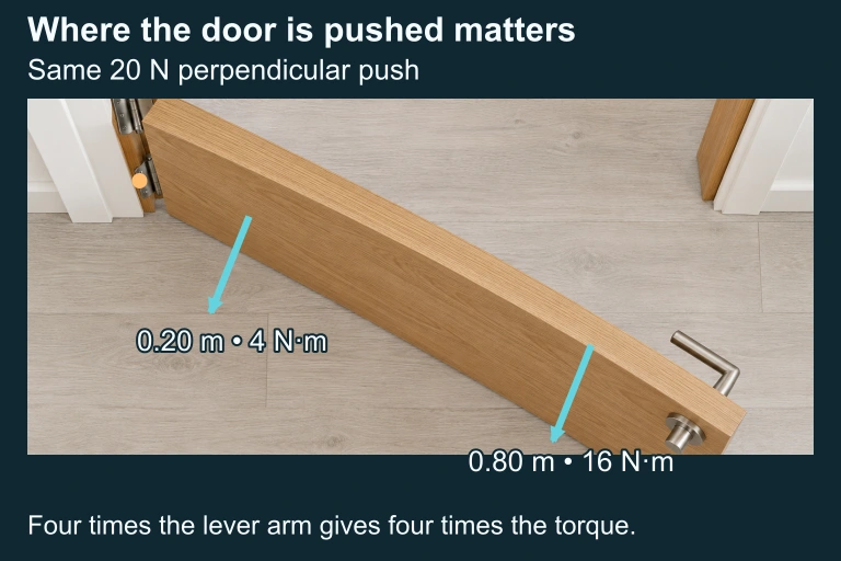 The same 20 N perpendicular force at lever arms 0.20 m and 0.80 m produces 4 N·m and 16 N·m.
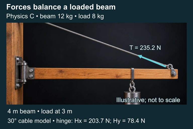 Physics C • beam 12 kg • load 8 kg; illustrative apparatus not to scale.
SECTION 4
Mathematical Framework
The mathematical structure of torque emerges naturally from extending Newton's second law to rotating systems. We begin with the vector definition, derive the scalar magnitude, and then connect torque to rotational dynamics through the moment of inertia.
TORQUE VECTOR DEFINITION
τ = torque vector (N·m), r = position vector from axis to point of force application (m), F = applied force vector (N). The cross product yields a vector perpendicular to both r and F.
SCALAR MAGNITUDE
θ = angle between r and F. The quantity d = r sin θ is the lever arm (moment arm) — the perpendicular distance from the axis to the line of action of the force.
NEWTON'S SECOND LAW FOR ROTATION
Στ = net torque about a given axis (N·m), I = moment of inertia about that axis (kg·m²), α = angular acceleration (rad/s²). This is the direct rotational analog of ΣF = ma.
A useful derivation connects the translational and rotational forms. Consider a single particle of mass m constrained to move in a circle of radius r. The tangential component of Newton's second law gives F⊥ = mat. Multiplying both sides by r yields rF⊥ = mrat. Since at = rα, we obtain τ = mr²α = Iα, confirming the rotational second law for a point mass with I = mr².
STATIC EQUILIBRIUM CONDITION
For a rigid body in static equilibrium, the net torque about any chosen axis must vanish. Combined with ΣF = 0, this gives a complete set of equilibrium conditions.
SECTION 5
Applications & Classification
Torque problems in AP Physics C fall into two broad categories: static equilibrium (Στ = 0) and rotational dynamics (Στ = Iα). In static equilibrium problems, you choose a convenient pivot, sum torques, and solve for unknown forces or distances. In dynamics problems, you combine torque equations with translational equations (often via a string-and-pulley constraint) to find angular or linear accelerations. The diagram below illustrates the classic Atwood machine with a massive pulley — one of the most commonly tested configurations on the AP exam.
| Problem Type | Key Condition | Typical Setup |
|---|---|---|
| Static Equilibrium | Στ = 0 and ΣF = 0 | Beam on supports, ladder against wall, sign hanging from a rod |
| Fixed-Axis Rotation | Στ = Iα about fixed axis | Pulley systems, rotating disks, rolling with slipping |
| Rolling Without Slipping | τ from friction; a = Rα constraint | Sphere or cylinder rolling down an incline |
| Angular Momentum | τ = dL/dt | Torque as the time derivative of angular momentum; precession |
Common torque problem categories on the AP Physics C exam
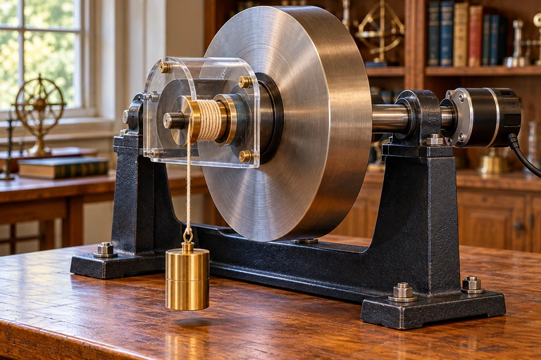 A hanging load’s tension is less than its weight while it accelerates downward. With no slip, a = rα, so its axle torque is m(g − rα)r.
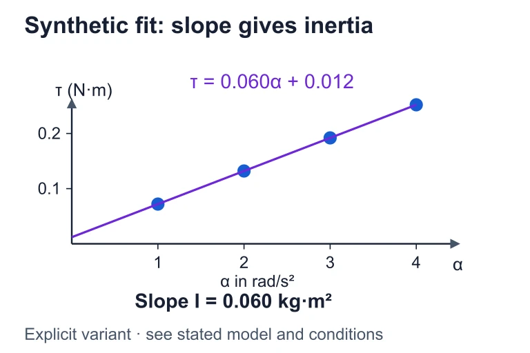 For the displayed relationship τ = 0.060α + 0.012, the slope gives I = 0.060 kg·m² and the intercept gives a constant opposing friction torque of 0.012 N·m.
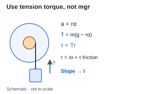 For a load accelerating downward, mg − T = ma. With no slip, a = rα, so the applied axle torque is Tr = m(g − rα)r. If bearing friction opposes rotation, Tr = Iα + τfriction.Open full diagram
SECTION 6
Worked Example
A uniform horizontal beam of mass M = 12 kg and length L = 4.0 m is attached to a wall by a hinge at its left end. A cable attached to the right end of the beam makes an angle of 30° with the beam and connects to the wall above the hinge. A block of mass m = 8.0 kg hangs from a point 3.0 m from the hinge. Find the tension in the cable and the force exerted by the hinge.
Worked example
- 1
Step 1 — Draw the Free-Body Diagram & Choose a Pivot
The beam has four forces: the beam's weight Mg acting downward at its center (2.0 m from hinge), the block's weight mg acting downward at 3.0 m from the hinge, the cable tension T at the right end (4.0 m), and the hinge force FH at the left end. We choose the hinge as the pivot to eliminate FH from the torque equation. - 2
Step 2 — Write the Torque Equation (Στ = 0 about hinge)
Taking counterclockwise as positive, the cable provides a CCW torque and the two weights provide CW torques. The perpendicular component of T relative to the beam is T sin 30°. Thus: T sin 30° × L − Mg × (L/2) − mg × (3.0 m) = 0. Substituting: T(0.50)(4.0) − (12)(9.8)(2.0) − (8.0)(9.8)(3.0) = 0.2.0T = 235.2 + 235.2 = 470.4 → T = 235.2 N - 3
Step 3 — Resolve the Tension into Components
Tx = T cos 30° = 235.2 × 0.866 = 203.7 N (horizontal, toward wall). Ty = T sin 30° = 235.2 × 0.50 = 117.6 N (vertical, upward). - 4
Step 4 — Apply ΣF = 0 to Find Hinge Forces
Horizontal: FHx − Tx = 0 → FHx = 203.7 N. Vertical: FHy + Ty − Mg − mg = 0 → FHy = (12 + 8)(9.8) − 117.6 = 196 − 117.6 = 78.4 N (upward).= √(203.7² + 78.4²) ≈ 218 N at 21° above horizontal
SECTION 7
Common Pitfalls & Problem-Solving Tips
| Common Mistake | Why It's Wrong | Correct Approach |
|---|---|---|
| Using τ = rF without the sin θ factor | This assumes the force is always perpendicular to the lever arm, which is only true when θ = 90°. | Always write τ = rF sin θ or compute the lever arm d = r sin θ first. |
| Choosing a pivot and forgetting it affects signs | Torques are measured about a specific point; changing the pivot changes the r for every force. | Pick a pivot that eliminates an unknown force, then consistently assign CCW as positive (or vice versa). |
| Assuming equal tensions on both sides of a massive pulley | A pulley with nonzero moment of inertia requires a net torque to accelerate, so T₁ ≠ T₂. | Write a separate torque equation for the pulley: (T₁ − T₂)R = Iα. |
| Confusing torque (N·m) with energy (J) | Both have the same SI units, but torque is a vector (cross product) while energy is a scalar (dot product). | Never convert between the two. Use N·m for torque and J for energy. |
| Neglecting the weight of a uniform beam in equilibrium problems | The beam's weight produces a torque about any pivot not at its center of mass. | Model the beam's weight as a single downward force Mg applied at its center of mass. |
Frequent errors and their corrections
Key takeaway
SECTION 8
Connection to Advanced Rotational Theory
At the AP Physics C level, torque connects to several deeper ideas that bridge the gap to upper-division mechanics. The relationship τ = dL/dt generalizes Newton's second law for rotation, relating torque to the time rate of change of angular momentum L. When the net external torque on a system is zero, angular momentum is conserved — a principle with applications ranging from figure skaters pulling in their arms to the precession of gyroscopes.
| AP Physics C Concept | Advanced Extension |
|---|---|
| τ = Iα (fixed axis) | Euler's equations for 3D rotation of rigid bodies with products of inertia |
| τ = dL/dt | Torque-free precession and nutation; gyroscopic stability analysis |
| Static equilibrium (Στ = 0) | Statically indeterminate systems requiring elasticity theory |
| Rolling without slipping (a = Rα) | Lagrangian mechanics with rolling constraints and generalized coordinates |
How AP-level torque concepts extend into upper-division physics
The work–energy theorem also has a rotational analog. The work done by a torque rotating through an angle dθ is dW = τ dθ, and integrating yields W = ∫τ dθ. For a constant torque, this simplifies to W = τΔθ. The rotational kinetic energy Krot = ½Iω² connects to work via the work–energy theorem: Wnet = ΔKrot. These relationships are frequently tested in FRQ problems that require translating between representations — for instance, deriving the angular velocity of a pulley system from energy methods rather than torque–acceleration kinematics.
SECTION 9
Practice Problems
Question 1: CONCEPTUAL
- A. It is halved.
- B. It remains the same.
- C. It is doubled.
- D. It is quadrupled.
Show answer (C)
Question 2: BASIC CALCULATION
- A. 16 N·m
- B. 27.7 N·m
- C. 32 N·m
- D. 24 N·m
Show answer (B)
Question 3: INTERMEDIATE
- A. g/L
- B. 2g/(3L)
- C. 3g/(2L)
- D. g/(2L)
Show answer (C)
Question 4: APPLIED
Show answer
Question 5: CRITICAL THINKING