

SECTION 1
Historical Context & Motivation
The study of motion becomes extraordinarily complex when multiple interacting bodies are involved—think of the planets in the solar system, the atoms in a gas, or the fragments of an exploding firework. Rather than tracking every individual particle, physicists developed the concept of the center of mass to distill the translational behavior of an entire system into the motion of a single representative point. This idea—that a distributed collection of matter behaves, in certain respects, as though all its mass were concentrated at one location—was a pivotal insight in the development of classical mechanics and remains indispensable in modern physics and engineering.
1687 • Newton's Principia
1748 • Euler's Rigid-Body Mechanics
1788 • Lagrange's Mécanique Analytique
1905 • Einstein's Special Relativity
The central question this lesson addresses is deceptively simple: when you push, pull, or fling a complex assembly of objects, which single point moves exactly as Newton's second law predicts for the whole collection? Answering this question unlocks a powerful strategy for analyzing collisions, explosions, rocket propulsion, and any scenario where internal forces complicate the picture.
SECTION 2
Core Principles & Definitions
Before diving into mathematical formalism, it is essential to establish the foundational ideas that underpin the center-of-mass framework. A system is any well-defined collection of particles or objects whose aggregate behavior we wish to study. Forces between members of the system are called internal forces, while forces exerted on the system by agents outside it are external forces. The beauty of Newton's third law is that all internal forces cancel in pairs when summed over the entire system, so only external forces affect the system's total momentum.
Center of Mass (COM)
Internal vs. External Forces
Newton's Second Law for Systems
Conservation of Momentum
KEY TAKEAWAY
SECTION 3
Visualizing the Center of Mass
The diagram below illustrates a two-particle system in two dimensions. Particle A has mass mA = 3 kg located at (1, 2) m and particle B has mass mB = 1 kg located at (5, 4) m. Because particle A is three times heavier, the center of mass lies three-quarters of the way from B toward A—closer to the heavier object. This geometric intuition is critical for quickly checking your algebra.
Notice how the center of mass at (2, 2.5) m sits on the line segment connecting the two particles, dividing it in the ratio mB : mA = 1 : 3 from A. This geometric fact is a quick sanity check: the center of mass is always closer to the more massive particle. If the two masses were equal, the COM would lie exactly at the midpoint (3, 3).
SECTION 4
Mathematical Framework
We now formalize the definitions introduced in Section 2. All equations below apply component-wise (i.e., independently for x, y, and z), but we present them in vector notation for compactness.
CENTER OF MASS POSITION (DISCRETE)
Here r⃗cm is the position vector of the center of mass, mᵢ is the mass of the i-th particle, r⃗ᵢ is its position vector, and M is the total system mass. Each component (x_cm, y_cm, z_cm) is computed separately.
CENTER OF MASS POSITION (CONTINUOUS)
For extended objects with continuously distributed mass, the sum becomes an integral over the body. The differential mass element dm can be expressed as λ dx (linear), σ dA (surface), or ρ dV (volume), depending on the geometry.
CENTER OF MASS VELOCITY
Differentiating the position equation yields the COM velocity, which equals the total linear momentum divided by the total mass. This equation makes momentum conservation geometrically intuitive: if p⃗_total is constant, v⃗_cm is constant.
NEWTON'S SECOND LAW FOR SYSTEMS
The net external force equals the total mass times the acceleration of the center of mass. Internal forces cancel by Newton's third law and do not appear. This is the master equation for analyzing any system of particles.
Derivation Sketch
SECTION 5
Center of Mass for Continuous Mass Distributions
Many AP Physics C problems involve objects with non-uniform mass distributions—a rod whose density increases linearly, a semicircular wire, or a triangular plate. In such cases, you replace the discrete sum with an integral. The key procedural steps are: (1) define a coordinate system with a convenient origin, (2) express dm in terms of a spatial variable using the given density function, (3) set up the integral for each component of r⃗_cm, and (4) evaluate. Symmetry arguments can often eliminate one or more components outright.
| Geometry | Density Element dm | COM Result (uniform density) |
|---|---|---|
| Thin rod (length L) | dm = λ dx | x_cm = L/2 |
| Semicircular wire (radius R) | dm = λ R dθ | y_cm = 2R/π |
| Semicircular disk (radius R) | dm = σ dA | y_cm = 4R/(3π) |
| Solid hemisphere (radius R) | dm = ρ dV | y_cm = 3R/8 |
| Triangular plate (height h) | dm = σ dA | y_cm = h/3 from base |
Common uniform-density shapes and their center-of-mass locations
 Center of mass weights each mass element by position, while rotational inertia weights it by squared distance from the axis. A removed region is subtracted from the original body with its own mass and location.
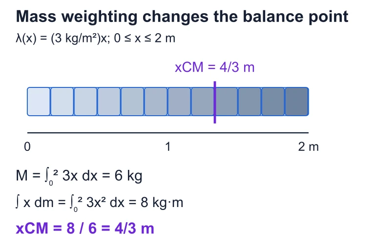 For λ(x) = (3 kg/m²)x on 0 ≤ x ≤ 2 m, integrating gives mass 6 kg and first moment 8 kg·m. The center of mass is at x = 4/3 m.
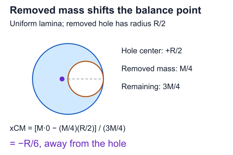 Removing a radius-R/2 hole centered at +R/2 from a uniform radius-R disk removes one-quarter of its mass. The remaining center of mass shifts to −R/6, away from the hole.
SECTION 6
Worked Example: Non-Uniform Rod
A thin rod of length L = 2.0 m has a linear mass density that varies as λ(x) = (3.0 kg/m²)x, where x is measured from the left end. Find the position of the center of mass.
Center of Mass of a Non-Uniform Rod
- 1
Step 1 — Identify the density function and limits
The linear mass density is λ(x) = (3.0 kg/m²)x. The rod extends from x = 0 to x = L = 2.0 m. The differential mass element is dm = λ(x) dx = (3.0)x dx. - 2
Step 2 — Compute the total mass M
M = ∫₀ᴸ λ(x) dx = ∫₀² (3.0)x dx = 3.0 × [x²/2]₀² = 3.0 × (4/2) = 3.0 × 2.0 = 6.0 kg.M = 6.0 kg - 3
Step 3 — Set up the numerator integral for x_cm
x_cm = (1/M) ∫₀ᴸ x dm = (1/M) ∫₀² x × (3.0)x dx = (1/M) ∫₀² 3.0 x² dx. - 4
Step 4 — Evaluate the integral
∫₀² 3.0 x² dx = 3.0 × [x³/3]₀² = 3.0 × (8/3) = 8.0 kg·m. Therefore x_cm = 8.0 / 6.0 = 4/3 m ≈ 1.33 m.x_cm = 4/3 m ≈ 1.33 m from the left end - 5
Step 5 — Interpret and verify
Since the density increases linearly from left to right, the COM should be to the right of the geometric center (L/2 = 1.0 m). Indeed, x_cm = 1.33 m > 1.0 m, which is exactly 2L/3—consistent with the general result for λ ∝ x. This confirms our calculation.
SECTION 7
Problem-Solving Strategies & Common Pitfalls
Center-of-mass problems on the AP exam often reward students who think strategically before computing. The table below contrasts effective approaches with common errors that lead to lost points.
| Effective Strategy | Common Pitfall |
|---|---|
| Exploit symmetry to eliminate one or more components of the COM integral without calculation. | Setting up a full 2D or 3D integral for a symmetric object, wasting time and inviting algebraic errors. |
| Use the composite-body method: treat an object with a hole as a full object minus the removed piece. | Attempting to integrate over the remaining shape directly, which may have complicated limits. |
| Check units at every step: dm must have units of kg, and x dm must have units of kg·m. | Confusing λ (kg/m), σ (kg/m²), and ρ (kg/m³), leading to dimensionally incorrect integrals. |
| Apply F_ext = M a_cm to analyze a system without free-body diagrams for every internal member. | Trying to find the acceleration of the whole system by summing internal forces (which cancel). |
| Verify that x_cm lies between the extreme positions and closer to the heavier mass or denser region. | Not performing a sanity check, so sign errors or integration mistakes go unnoticed. |
Strategies vs. pitfalls in center-of-mass problems
KEY TAKEAWAY
SECTION 8
Connection to Momentum, Collisions, and Beyond
The center-of-mass framework does far more than locate a balance point—it is the conceptual bridge between single-particle dynamics and the rich phenomena of multi-body systems. In collisions, the center-of-mass reference frame (also called the zero-momentum frame) simplifies analysis because the total momentum is zero by construction. This is the standard frame used in particle physics to characterize the energy available for creating new particles. In rocket propulsion, the Tsiolkovsky rocket equation is derived by treating the rocket and its exhaust as a system whose center of mass obeys Newton's second law with no external horizontal forces (in the idealized case).
| This Lesson (AP C Mechanics) | Advanced Extension |
|---|---|
| Discrete sum: r⃗_cm = (1/M) Σ mᵢ r⃗ᵢ | Continuous fields: r⃗_cm = (1/M) ∫ r⃗ ρ(r⃗) dV over arbitrary density distributions; used in astrophysics for galaxy modeling. |
| F_ext = M a_cm in an inertial frame | In the COM frame, the total kinetic energy splits into K_cm (translational KE of COM) + K_int (KE relative to COM). This decomposition underpins the energy analysis of collisions. |
| Conservation of momentum when F_ext = 0 | Relativistic four-momentum conservation; center-of-momentum frame in special relativity, where the invariant mass √(s) = E_cm / c² determines collision thresholds. |
| Composite-body subtraction for objects with holes | Tensor of inertia formulations using the parallel axis theorem, which requires the COM as a reference. Central to rigid-body rotational dynamics. |
Bridging AP Mechanics to advanced physics
As you progress to rotational dynamics later in the AP C course, you will see that the center of mass plays an equally fundamental role: the torque equation τ = Iα is simplest when torques are computed about the center of mass, and the kinetic energy of a rolling object decomposes naturally into translational kinetic energy (½Mv²_cm) and rotational kinetic energy (½Iω²) about the COM. Mastering the material in this lesson therefore pays dividends across the entire mechanics curriculum.
SECTION 9
Practice Problems
Question 1: CONCEPTUAL
- A. The center of mass moves toward the heavier skater because that skater exerts a larger force.
- B. The center of mass moves toward the lighter skater because that skater moves faster.
- C. The center of mass remains stationary because there is no net external force on the system.
- D. The center of mass accelerates in the direction of the net internal force.
Show answer (C)
Question 2: BASIC CALCULATION
- A. 4.0 m
- B. 5.2 m
- C. 6.0 m
- D. 3.6 m
Show answer (B)
Question 3: INTERMEDIATE
- A. R/6 away from the hole
- B. R/4 away from the hole
- C. R/3 toward the hole
- D. R/8 away from the hole
Show answer (A)
Question 4: APPLIED
10 ptsShow answer
Question 5: CRITICAL THINKING
7 ptsShow answer
SUMMARY
Lesson Summary
Summary
The center of mass is the mass-weighted average position of a system, defined by r⃗_cm = (1/M) Σ mᵢ r⃗ᵢ for discrete particles and by r⃗_cm = (1/M) ∫ r⃗ dm for continuous bodies. Newton's second law for systems, F⃗_ext = M a⃗_cm, tells us that only external forces can change the motion of the center of mass, because internal forces cancel pairwise by Newton's third law.
When the net external force is zero, total momentum is conserved and the center of mass moves at constant velocity (or remains at rest). For continuous mass distributions, express dm in terms of a density function (λ, σ, or ρ) and integrate. The composite-body technique (full object minus removed piece with 'negative mass') is a powerful shortcut for objects with holes. Always verify that your computed COM lies closer to regions of greater mass—this quick sanity check catches algebraic errors before they cost points on the exam.