
SECTION 1
Historical Context & Motivation
The study of rotating bodies has fascinated natural philosophers since antiquity, but a rigorous mathematical treatment of rotational inertia — sometimes called the moment of inertia — only crystallized during the Scientific Revolution. Early engineers intuitively understood that the distribution of mass in a flywheel mattered as much as the total mass itself: a heavy rim spun more steadily than a heavy hub. Translating that intuition into precise mathematics required the simultaneous development of calculus and Newtonian mechanics, and it took nearly two centuries for the concept to reach its modern form.
1673 • Huygens' Compound Pendulum
1749 • Euler Formalizes Rigid-Body Rotation
1834 • Parallel-Axis Theorem
1850s • Industrial Flywheel Engineering
These developments converged on a central question that remains at the heart of rotational dynamics: given a rigid body of known geometry and mass distribution, how do we quantify its resistance to angular acceleration about any chosen axis? That quantity — the rotational inertia — is the subject of this lesson.
SECTION 2
Core Principles & Definitions
In translational mechanics, mass alone determines how strongly an object resists acceleration under a net force (Newton's second law, F = ma). In rotational mechanics, the analogous role is played by the moment of inertia, commonly denoted I. However, unlike mass, I depends not only on how much matter an object contains but also on how that matter is distributed relative to the axis of rotation. Two objects of identical mass can have dramatically different moments of inertia if their geometries differ.
Definition of I
Axis Dependence
Newton's 2nd Law (Rotation)
Additive Property
SECTION 3
Visual Explanation — Mass Distribution & the Rotation Axis
The diagram above encapsulates the single most important idea in this topic: rotational inertia depends on the square of the distance from each mass element to the chosen rotation axis. Doubling a particle's distance from the axis quadruples its contribution to I. This r² dependence explains why a thin-walled cylindrical shell (all mass at radius R) has a moment of inertia of MR², whereas a solid cylinder of the same mass and radius has only ½MR² — its inner mass elements contribute less because they sit closer to the axis.
SECTION 4
Mathematical Framework
Discrete and Continuous Definitions
DISCRETE SYSTEM
mᵢ = mass of the i-th particle; rᵢ = perpendicular distance of particle i from the rotation axis. Units: kg·m².
CONTINUOUS BODY
dm is an infinitesimal mass element at perpendicular distance r from the axis. For uniform density ρ, dm = ρ dV, enabling conversion to a volume integral.
The transition from summation to integration is the natural step when moving from a finite collection of point masses to a continuous mass distribution. For bodies with uniform linear mass density λ (rods), surface mass density σ (plates), or volume mass density ρ (solids), the integral is converted using dm = λ dx, dm = σ dA, or dm = ρ dV, respectively. Choosing coordinates that exploit the body's symmetry simplifies evaluation considerably.
Parallel-Axis Theorem
PARALLEL-AXIS THEOREM
I_cm = moment of inertia about an axis through the center of mass; M = total mass; d = perpendicular distance between the center-of-mass axis and the new parallel axis. This theorem always increases I relative to the center-of-mass value.
Perpendicular-Axis Theorem (Planar Bodies Only)
PERPENDICULAR-AXIS THEOREM
Valid only for flat (planar) bodies lying in the x-y plane. is the moment about the axis perpendicular to the plane, while and are about two mutually perpendicular axes in the plane. All three axes intersect at a common point.
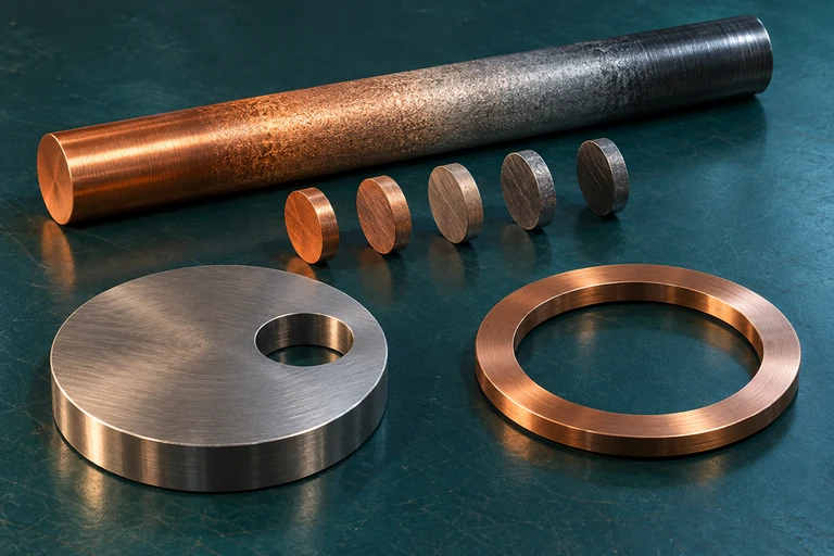 Compute rotational inertia by integrating squared distance from the selected axis against mass. Shifting to a parallel axis adds Md² to the central moment of inertia.
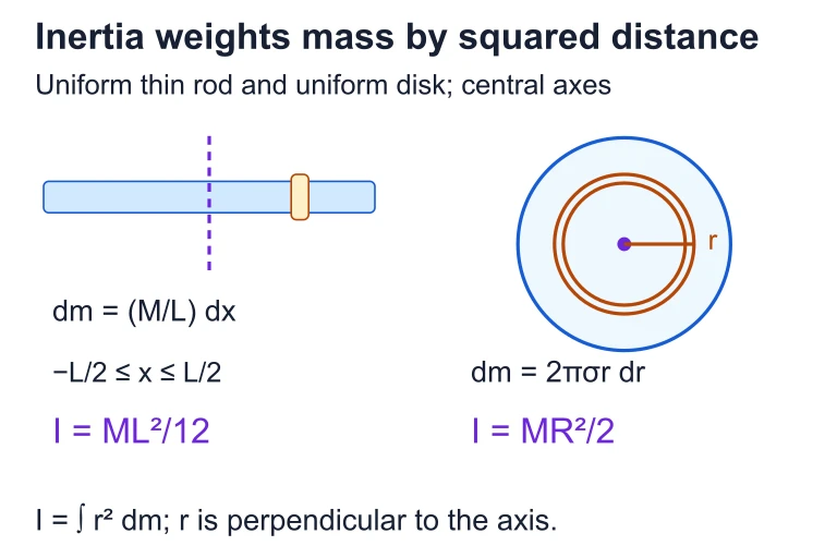 A uniform rod about its central transverse axis has I = ML²/12, while a uniform disk about its central normal axis has I = MR²/2. The rod uses dm = (M/L)dx; the disk uses annular elements dm = 2πσr dr.
SECTION 5
Moments of Inertia for Standard Geometries
Certain geometric shapes appear so frequently in physics and engineering that their moments of inertia are worth committing to memory — or at least recognizing on sight. The table below lists the most important results, all of which can be derived through direct integration.
| Shape | Axis | Moment of Inertia |
|---|---|---|
| Thin hoop (ring), mass M, radius R | Through center, perpendicular to plane | MR² |
| Solid disk / cylinder, mass M, radius R | Central symmetry axis | ½MR² |
| Thin-walled hollow cylinder, mass M, radius R | Central symmetry axis | MR² |
| Solid sphere, mass M, radius R | Any diameter | ⅖MR² |
| Thin spherical shell, mass M, radius R | Any diameter | ⅔MR² |
| Uniform thin rod, mass M, length L | Through center, perpendicular to rod | ¹⁄₁₂ML² |
| Uniform thin rod, mass M, length L | Through one end, perpendicular to rod | ⅓ML² |
Standard moments of inertia for common rigid bodies
Notice a pattern in the table: shapes where mass is concentrated farther from the axis (hoops, shells) have larger numerical prefactors than their solid counterparts (disks, spheres). The numerical coefficient reflects the average value of r²/R² over the body's geometry. A thin hoop places all mass at r = R, giving a prefactor of 1, whereas a solid disk averages over 0 ≤ r ≤ R, yielding ½.
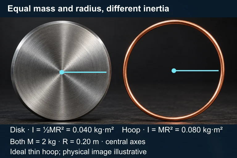 For equal mass 2 kg and radius 0.20 m about central axes, a solid disk has I = 0.040 kg·m² and a thin hoop has I = 0.080 kg·m².
SECTION 6
Worked Example — Compound Pulley System
A solid disk of mass M = 4.0 kg and radius R = 0.25 m is mounted on a frictionless axle through its center. A light, inextensible string is wrapped around the disk's rim, and a hanging block of mass m = 2.0 kg is attached to the free end. Find the angular acceleration of the disk and the linear acceleration of the block when the system is released from rest.
Worked example
- 1
Step 1 — Identify the Moment of Inertia
The disk rotates about its central axis, so I = ½MR² = ½(4.0)(0.25)² = 0.125 kg·m².I = 0.125 kg·m² - 2
Step 2 — Free-Body Analysis of the Block
For the hanging block (taking downward as positive): mg − T = ma, where T is the string tension and a is the linear acceleration. - 3
Step 3 — Torque on the Disk
The string exerts torque τ = TR on the disk. Applying Newton's second law for rotation: TR = Iα. Since the string doesn't slip, a = Rα, so α = a/R. - 4
Step 4 — Solve for Acceleration
Substituting α = a/R into the torque equation: TR = I(a/R), giving T = Ia/R². Substituting into the block equation: mg − Ia/R² = ma. Solving for a: a = mg/(m + I/R²) = (2.0)(9.8)/(2.0 + 0.125/0.0625) = 19.6/(2.0 + 2.0) = 4.9 m/s².a = 4.9 m/s² - 5
Step 5 — Angular Acceleration
α = a/R = 4.9/0.25 = 19.6 rad/s².α = 19.6 rad/s² - 6
Step 6 — Verify with Energy (Sanity Check)
Note that if the disk were massless (I → 0), the block would free-fall at g = 9.8 m/s². Our answer of 4.9 m/s² = g/2 makes sense because I/R² = 2.0 kg, equal to m — the effective rotational mass of the disk equals the hanging mass, halving the acceleration.
SECTION 7
Translational vs. Rotational Analogies
One of the most powerful strategies in rotational dynamics is recognizing the direct parallels between translational and rotational quantities. Nearly every translational equation has a rotational counterpart obtained by the substitutions shown below. Mastering this mapping streamlines problem-solving and deepens conceptual understanding.
| Translational Quantity | Rotational Analog | Key Equation |
|---|---|---|
| Mass, m | Moment of inertia, I | I = ∫ r² dm |
| Force, F | Torque, τ | τ = r × F |
| Acceleration, a | Angular acceleration, α | α = d²θ/dt² |
| Newton's 2nd: F = ma | τ_net = Iα | Rotational form of Newton's 2nd law |
| Kinetic energy: ½mv² | Rotational KE: ½Iω² | For rolling: KE = ½mv² + ½Iω² |
| Momentum: p = mv | Angular momentum: L = Iω | For a rigid body about a fixed axis |
Translational–Rotational analogy table
SECTION 8
Connection to the Inertia Tensor & Beyond
In AP Physics C, rotational inertia is treated as a scalar quantity about a fixed axis. However, in more advanced mechanics the moment of inertia generalizes to a second-rank tensor — the inertia tensor. This 3 × 3 symmetric matrix encodes how the body resists angular acceleration about any axis simultaneously. The diagonal elements are the moments of inertia about the coordinate axes, while the off-diagonal elements (products of inertia) capture coupling between different rotation axes. When the coordinate system aligns with the body's principal axes, all products of inertia vanish and the tensor becomes diagonal.
| Feature | AP Physics C (Scalar I) | Advanced Mechanics (Tensor I) |
|---|---|---|
| Dimension | Single scalar for a given axis | 3 × 3 symmetric matrix (6 independent components) |
| Applicable to | Fixed-axis rotation | Arbitrary 3D rotation, precession, nutation |
| Angular momentum | L = Iω (scalar equation) | L⃗ = [I]ω⃗ (matrix equation; L⃗ may not be parallel to ω⃗) |
| Key theorems | Parallel-axis, perpendicular-axis | Generalized parallel-axis; diagonalization via principal axes |
Scalar vs. tensor treatment of rotational inertia
You do not need the inertia tensor for the AP exam, but understanding that it exists helps you appreciate why the scalar treatment applies only to fixed-axis or symmetric-body problems. When you encounter wobbling tops, gyroscopic precession, or satellite tumbling in college-level classical mechanics (e.g., in a course using Goldstein or Taylor), the inertia tensor is the tool you will reach for.
SECTION 9
Practice Problems
Question 1: CONCEPTUAL
- A. Cylinder A, by a factor of 2
- B. Cylinder A, by a factor of 4
- C. Cylinder B, by a factor of 2
- D. Both have the same angular acceleration
Show answer (B)
Question 2: BASIC CALCULATION
- A. 0.36 kg·m²
- B. 1.08 kg·m²
- C. 1.44 kg·m²
- D. 4.32 kg·m²
Show answer (C)
Question 3: INTERMEDIATE
- A. 1/5
- B. 2/7
- C. 2/5
- D. 5/7
Show answer (B)
Question 4: APPLIED
Show answer
Question 5: CRITICAL THINKING