

SECTION 1
Historical Context & Motivation
Newton's 1687 masterpiece, the Principia Mathematica, established the foundational relationship between force and linear acceleration, yet it took more than a century of subsequent mathematical development before physicists articulated the full rotational analog of the second law. The challenge was not merely conceptual but deeply mathematical: while a point particle's inertia is captured by a single scalar mass, the resistance of an extended body to angular acceleration depends on how that mass is distributed relative to the axis of rotation. Unifying these ideas required contributions from Euler, Lagrange, and many others who developed the formal apparatus of rigid-body mechanics. The resulting equation, τ_net = Iα, is now regarded as the cornerstone of rotational dynamics and is essential to analyzing everything from spinning tops to spacecraft attitude control.
1687 • Newton's Principia
1750 • Euler's Rigid-Body Equations
1788 • Lagrange's Mécanique Analytique
1834 • Hamilton's Principle
The central question that motivated all of this development was deceptively simple: if a force applied to a point mass produces a linear acceleration proportional to that force divided by the mass, what governs the angular acceleration of a rigid body subject to a turning influence? The answer involves two new quantities — torque as the rotational analog of force, and moment of inertia as the rotational analog of mass — woven together in a single, elegant equation that mirrors the familiar F = ma.
SECTION 2
Core Principles & Definitions
Before diving into the mathematics, it is essential to establish the conceptual pillars that underpin Newton's second law in rotational form. Each quantity in the equation τnet = Iα has a direct linear counterpart, and understanding these parallels is the fastest route to physical intuition. The four core ideas below form the conceptual scaffold for everything that follows.
Torque (τ)
Moment of Inertia (I)
Angular Acceleration (α)
The Rotational Second Law
KEY TAKEAWAY
SECTION 3
Visual Explanation — Torque and Angular Acceleration
The diagram above captures the essential geometry of rotational dynamics. The position vector r (violet) runs from the axis of rotation to the point where force F (red) is applied. The cross product r × F gives the torque, whose magnitude depends on the sine of the angle between the two vectors — this is why a force applied perpendicularly to the lever arm generates the maximum torque. The resulting angular acceleration α (cyan) is inversely proportional to the moment of inertia I of the disk: a disk with mass concentrated at the rim has a larger I and thus accelerates more slowly for the same applied torque. Notice the complete analogy with the linear case: net force produces linear acceleration in proportion to 1/m, and net torque produces angular acceleration in proportion to 1/I.
SECTION 4
Mathematical Framework
The rotational second law can be derived directly from Newton's second law applied to each infinitesimal mass element of a rigid body. Consider a rigid body rotating about a fixed axis. For a small mass element dm at perpendicular distance r from the axis, the tangential component of the net force satisfies dFt = dm × at = dm × rα, where at = rα is the tangential acceleration. Multiplying both sides by r gives dτ = r² α dm. Integrating over the entire body yields the rotational second law.
TORQUE DEFINITION
r = position vector from axis to point of force application; F = applied force; θ = angle between r and F. The direction of τ is given by the right-hand rule and points along the axis of rotation.
MOMENT OF INERTIA
r = perpendicular distance from each mass element to the rotation axis. I depends on the choice of axis — use the parallel axis theorem (I = Icm + Md²) to shift between axes.
NEWTON'S SECOND LAW — ROTATIONAL FORM
Στ = net external torque about the chosen axis (N·m); I = moment of inertia about that axis (kg·m²); α = angular acceleration (rad/s²). This equation holds for rotation about a fixed axis or about the center of mass of a translating-and-rotating body.
DERIVATION SUMMARY
The angular acceleration α factors out of the integral because all parts of a rigid body share the same α. The remaining integral ∫r² dm is precisely the moment of inertia I.
Calculus Connection
SECTION 5
Linear–Rotational Analogy & Common Moments of Inertia
One of the most powerful strategies for mastering rotational dynamics is to map every linear quantity to its rotational counterpart. The table below provides a systematic translation; once you internalize this mapping, almost every rotational problem reduces to a familiar linear structure with renamed variables. Following the analogy table, a second diagram summarizes the moments of inertia for shapes that appear frequently on the AP Physics C exam.
| Linear Quantity | Symbol | Rotational Quantity | Symbol |
|---|---|---|---|
| Displacement | x | Angular displacement | θ |
| Velocity | v | Angular velocity | ω |
| Acceleration | a | Angular acceleration | α |
| Mass (inertia) | m | Moment of inertia | I |
| Force | F | Torque | τ |
| Momentum | p = mv | Angular momentum | L = Iω |
| Newton's 2nd Law | F = ma | Newton's 2nd (rot.) | τ = Iα |
Linear–Rotational Analogy Table
A useful pattern to notice is that the moment of inertia for any standard shape can be written as I = cMR² (or cML² for rods), where c is a dimensionless constant between 0 and 1 that encodes how mass is distributed relative to the axis. A thin hoop, with all mass at radius R, has c = 1, whereas a solid disk has c = ½ because its mass is spread from r = 0 to r = R. This pattern makes it easy to compare objects: if two objects have the same mass and radius, the one with the larger c has a larger moment of inertia and will undergo a smaller angular acceleration for the same applied torque.
SECTION 6
Worked Example — Atwood Machine with a Massive Pulley
The classic Atwood machine with a massive pulley is a staple of AP Physics C: Mechanics because it simultaneously tests Newton's second law in both linear and rotational forms. Two blocks of mass m1 = 4.0 kg and m2 = 2.0 kg are connected by a massless string draped over a uniform solid disk pulley of mass M = 3.0 kg and radius R = 0.20 m. Find the angular acceleration of the pulley, the linear acceleration of the blocks, and the tension on each side of the string. Assume the string does not slip on the pulley.
Atwood Machine with Massive Pulley
- 1
Step 1 — Identify the system and draw free-body diagrams
There are three objects: block 1 (4 kg, on the left, accelerates downward), block 2 (2 kg, on the right, accelerates upward), and the pulley (rotates counterclockwise). The string exerts different tensions T1 and T2 on each side because the pulley has mass. The no-slip condition links linear and angular quantities: a = Rα. - 2
Step 2 — Write Newton's second law for each block
For block 1 (taking downward as positive): m1g − T1 = m1a. For block 2 (taking upward as positive): T2 − m2g = m2a. - 3
Step 3 — Write the rotational second law for the pulley
The net torque on the pulley comes from the two tensions acting at radius R. Taking counterclockwise as positive: T1R − T2R = Iα. For a uniform solid disk, I = ½MR². Using the no-slip condition α = a/R, this becomes (T1 − T2)R = ½MR²(a/R), which simplifies to T1 − T2 = ½Ma. - 4
Step 4 — Solve the system of three equations
Adding the three equations eliminates both tensions: m1g − m2g = (m1 + m2 + ½M)a. Substituting values: (4.0 − 2.0)(9.8) = (4.0 + 2.0 + 1.5)a → 19.6 = 7.5a → a = 2.61 m/s².a = 2.61 m/s² - 5
Step 5 — Find the angular acceleration
Using the no-slip condition: α = a/R = 2.61/0.20 = 13.1 rad/s².α = 13.1 rad/s² - 6
Step 6 — Find the tensions
From the block 1 equation: T1 = m1(g − a) = 4.0(9.8 − 2.61) = 28.8 N. From the block 2 equation: T2 = m2(g + a) = 2.0(9.8 + 2.61) = 24.8 N. Note that T1 > T2, as expected — the tension difference provides the net torque to accelerate the pulley.T₁ = 28.8 N, T₂ = 24.8 N
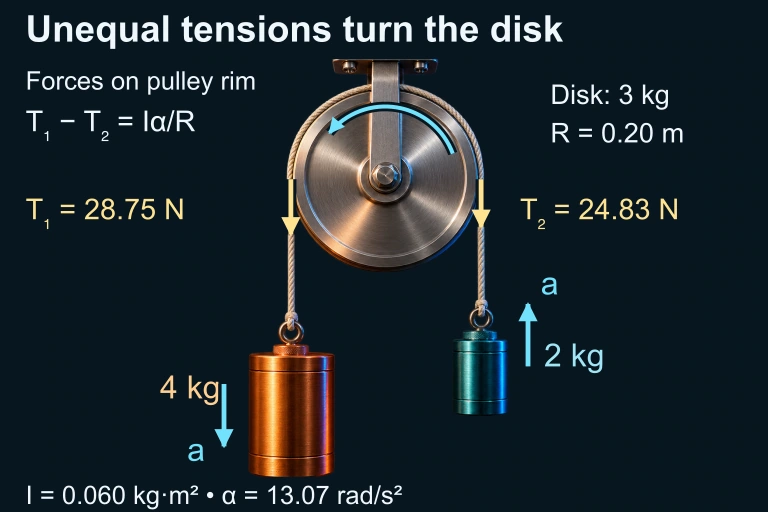 AP Physics C massive pulley: a 4 kg block on the left descends and a 2 kg block rises. With disk M = 3 kg and R = 0.20 m, T₁ = 28.75 N, T₂ = 24.83 N and α = 13.07 rad/s² counterclockwise. The AP Physics 1 companion has one hanging mass.
 For two loads linked over a massive pulley, unequal tensions supply the net pulley torque. With the heavier load labeled 1, combine the load equations with (T₁ − T₂)R = Iα and the no-slip condition a = Rα.
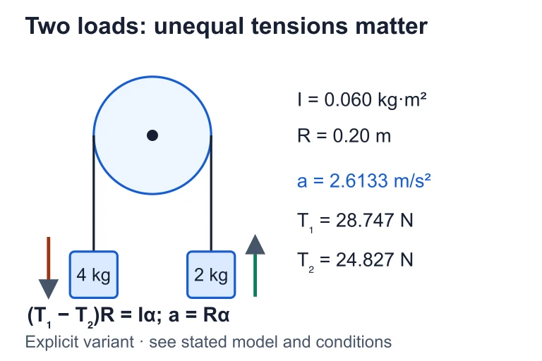 For loads 4 kg and 2 kg, I = 0.060 kg·m² and R = 0.20 m, acceleration is about 2.6133 m/s². Tensions 28.747 N and 24.827 N satisfy (T₁ − T₂)R = Iα and a = Rα.
SECTION 7
Common Pitfalls & Exam Tips
Rotational dynamics problems are among the most error-prone on the AP Physics C exam, not because the underlying physics is more difficult than linear mechanics, but because students frequently confuse sign conventions, forget constraint equations, or use the wrong moment of inertia. The table below catalogs the most common mistakes alongside the correct approach, and the key takeaway afterward offers a unifying strategy for avoiding them.
| Common Pitfall | Why It's Wrong | Correct Approach |
|---|---|---|
| Using τ = rF instead of τ = rF sin θ | Only the perpendicular component of F contributes to torque; the radial component does not cause rotation. | Always decompose forces or use the cross product formula |τ| = rF sin θ. |
| Assuming equal tensions on both sides of a massive pulley | Equal tensions mean zero net torque, so the pulley would not accelerate angularly — inconsistent with the blocks accelerating. | Write separate tension variables (T₁, T₂) and use the rotational equation to relate them. |
| Using the wrong axis for I | I depends on the axis of rotation; a formula derived for the center of mass won't work for an end-pivot without correction. | Apply the parallel axis theorem: I = I_cm + Md². |
| Forgetting the no-slip constraint | Without a = Rα, you have more unknowns than equations and the system is unsolvable. | Always state the constraint a = Rα (or v = Rω) explicitly before solving. |
| Inconsistent sign conventions | Mixing up positive directions for translation and rotation leads to sign errors in the final answer. | Choose a consistent positive direction (e.g., if block 1 descends is positive, clockwise rotation of the pulley is positive). |
Common Rotational Dynamics Pitfalls
EXAM STRATEGY
SECTION 8
Connection to Angular Momentum & Beyond
Newton's second law in rotational form, Στ = Iα, is actually a special case of a deeper and more general principle: the rate of change of angular momentum equals the net external torque. When the moment of inertia is constant, the general law Στ = dL/dt reduces to our familiar Iα form. However, many physical situations involve changing moments of inertia — a collapsing star, a figure skater pulling in their arms, or a satellite deploying solar panels — and for these, you must use the full angular momentum formulation. The table below contrasts the two frameworks.
| Feature | Στ = Iα (Fixed I) | Στ = dL/dt (General) |
|---|---|---|
| Applicability | Rigid body with fixed axis or rotation about the center of mass | Any system, including deformable bodies and those with changing I |
| Moment of inertia | Constant | May vary with time |
| Conservation law | If Στ = 0, then α = 0 (constant ω) | If Στ = 0, then L = Iω = constant (ω can change if I changes) |
| AP exam relevance | Accounts for the majority of torque/rotation problems on the exam | Required for angular momentum conservation problems and impulse-momentum rotational analogs |
| Vector generalization | Scalar version sufficient for fixed-axis problems | Full vector treatment needed for precession and 3D rotation (Euler's equations) |
Comparing τ = Iα with the general angular momentum formulation
Looking forward, you will encounter situations where an object both translates and rotates — for example, a ball rolling down an incline or a yo-yo unwinding. In these cases, you apply Newton's second law for translation (ΣF = macm) and for rotation about the center of mass (Στcm = Icmα) simultaneously. This dual application, combined with energy methods involving rotational kinetic energy (Krot = ½Iω²), forms the complete toolkit for rigid-body dynamics on the AP Physics C exam and in any introductory university course.
SECTION 9
Practice Problems
Question 1: CONCEPTUAL
- A. The disk has exactly twice the angular acceleration of the hoop.
- B. The hoop has exactly twice the angular acceleration of the disk.
- C. Both objects have the same angular acceleration because they have the same mass.
- D. The disk has four times the angular acceleration of the hoop.
Show answer (A)
Question 2: BASIC CALCULATION
- A. 6.0 rad/s²
- B. 12 rad/s²
- C. 24 rad/s²
- D. 48 rad/s²
Show answer (B)
Question 3: INTERMEDIATE
- A. 8.2 rad/s²
- B. 12.3 rad/s²
- C. 16.3 rad/s²
- D. 24.5 rad/s²
Show answer (B)
Question 4: APPLIED
5 ptsShow answer
Question 5: CRITICAL THINKING
4 ptsShow answer
SUMMARY
Lesson Summary
Summary
Newton's second law in rotational form, Στ = Iα, states that the net external torque about a chosen axis equals the product of the moment of inertia about that axis and the angular acceleration. Torque is computed as τ = r × F (magnitude rF sin θ), and the moment of inertia is found from I = ∫r² dm or standard formulas for common shapes (disk: ½MR², hoop: MR², sphere: ⅖MR², rod about center: ¹⁄₁₂ML², rod about end: ⅓ML²).
When solving problems that couple translation and rotation — such as Atwood machines with massive pulleys or objects rolling without slipping — apply ΣF = ma for translation and Στ = Iα for rotation simultaneously, linked by the constraint equation a = Rα. This law is a special case of the more general Στ = dL/dt (valid even when I changes), which underpins conservation of angular momentum when the net external torque is zero.