01 / 21

Electromagnetic
Induction & Faraday's Law

Discover how changing magnetic fields create electric currents: the principle behind generators, transformers, and modern technology.

AP Physics 2

What Is Electromagnetic Induction?

Electromagnetic induction is the process by which a changing magnetic flux through a circuit produces an electromotive force (EMF) and, if the circuit is closed, an induced current. Discovered by Michael Faraday in 1831, it is one of the most important phenomena in physics.

Magnetic Flux: \(\Phi_B\)

Magnetic flux measures how much magnetic field passes through a surface. It depends on the field strength, the area, and the angle between them:

\(\hat{n}\) \(\vec{B}\) \(\theta\) Area \(A\) Unit: Wb (Weber) = \(\text{T}\cdot\text{m}^2\)

How Does Flux Change?

Since \(\Phi_B = B \cdot A \cdot \cos\theta\), the flux changes when any of its three factors changes:

\(B\) Changes
The magnetic field strength increases or decreases (e.g., moving a magnet closer or farther).
\(A\) Changes
The effective area of the loop changes (e.g., stretching or compressing a flexible loop).
\(\theta\) Changes
The loop rotates relative to the field (e.g., a generator spinning inside a magnetic field).

Faraday's Law of Induction

The magnitude of the induced EMF depends on how rapidly the flux changes. Faster changes produce larger EMFs.

Visualizing Faraday's Law

\(N\) \(S\) push toward coil \(I_{\text{induced}}\) Galvanometer Moving magnet \(\rightarrow\) changing \(\Phi_B \rightarrow \mathcal{E}\)

Lenz's Law: The Direction Rule

Lenz's Law states that the direction of the induced current is such that it opposes the change in magnetic flux that caused it. This is a consequence of conservation of energy.

1
Identify the change: Is the flux through the loop increasing or decreasing?
2
Oppose the change: The induced current creates a magnetic field that opposes the flux change.
3
Use the right-hand rule: Curl your fingers in the direction of induced current; your thumb points in the direction of the induced \(\vec{B}\).

Eddy-current drag

As the plate enters the into-page field, induced currents oppose the flux increase. Slots interrupt large paths; the removed material also changes mass.
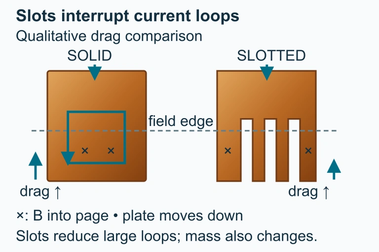
Falling magnet/plate induces current opposing increasing into-page flux; CCW current, outward induced B and upward drag.
As a conducting plate enters an into-page field, eddy currents oppose the change. Slots interrupt large paths, reducing qualitative drag; removed material also changes mass.

Faraday vs. Lenz

Faraday's Law Lenz's Law
Tells you Magnitude of induced EMF Direction of induced current
Formula \(\mathcal{E} = -N\,\dfrac{d\Phi_B}{dt}\) Encoded in the negative sign
Physical basis Experimental observation Conservation of energy
Key question How much EMF? Which way does current flow?

How to Apply Faraday's Law

1
Identify the loop: What area is enclosed? How many turns \(N\)?
2
Write the flux: Express \(\Phi_B = B \cdot A \cdot \cos\theta\) using the given variables.
3
Find the change: Determine which quantity (\(B\), \(A\), or \(\theta\)) is changing with time.
4
Differentiate: Compute \(\dfrac{d\Phi_B}{dt}\) and multiply by \(-N\) to get \(\mathcal{E}\).
5
Apply Lenz's Law: Use the right-hand rule to find the direction of induced current.

Example 1: Changing Field

A circular loop of radius \(r = 0.10\) m sits perpendicular to a uniform magnetic field that increases from \(B = 0.20\) T to \(B = 0.50\) T in \(\Delta t = 0.30\) s. Find the induced EMF.

1
Area: \(A = \pi r^2 = \pi(0.10)^2 = 0.0314 \text{ m}^2\)
2
Change in flux: \(\Delta\Phi_B = \Delta B \cdot A = (0.50 - 0.20)(0.0314) = 0.00942 \text{ Wb}\)
3
Induced EMF: \(\displaystyle|\mathcal{E}| = \frac{\Delta\Phi_B}{\Delta t} = \frac{0.00942}{0.30} \approx 0.031 \text{ V}\)

Example 2: Rotating Loop

A rectangular coil with \(N = 50\) turns and area \(A = 0.04\) m² rotates in a uniform field of \(B = 0.30\) T. The coil rotates at angular velocity \(\omega = 120\pi\) rad/s. Find the peak EMF.

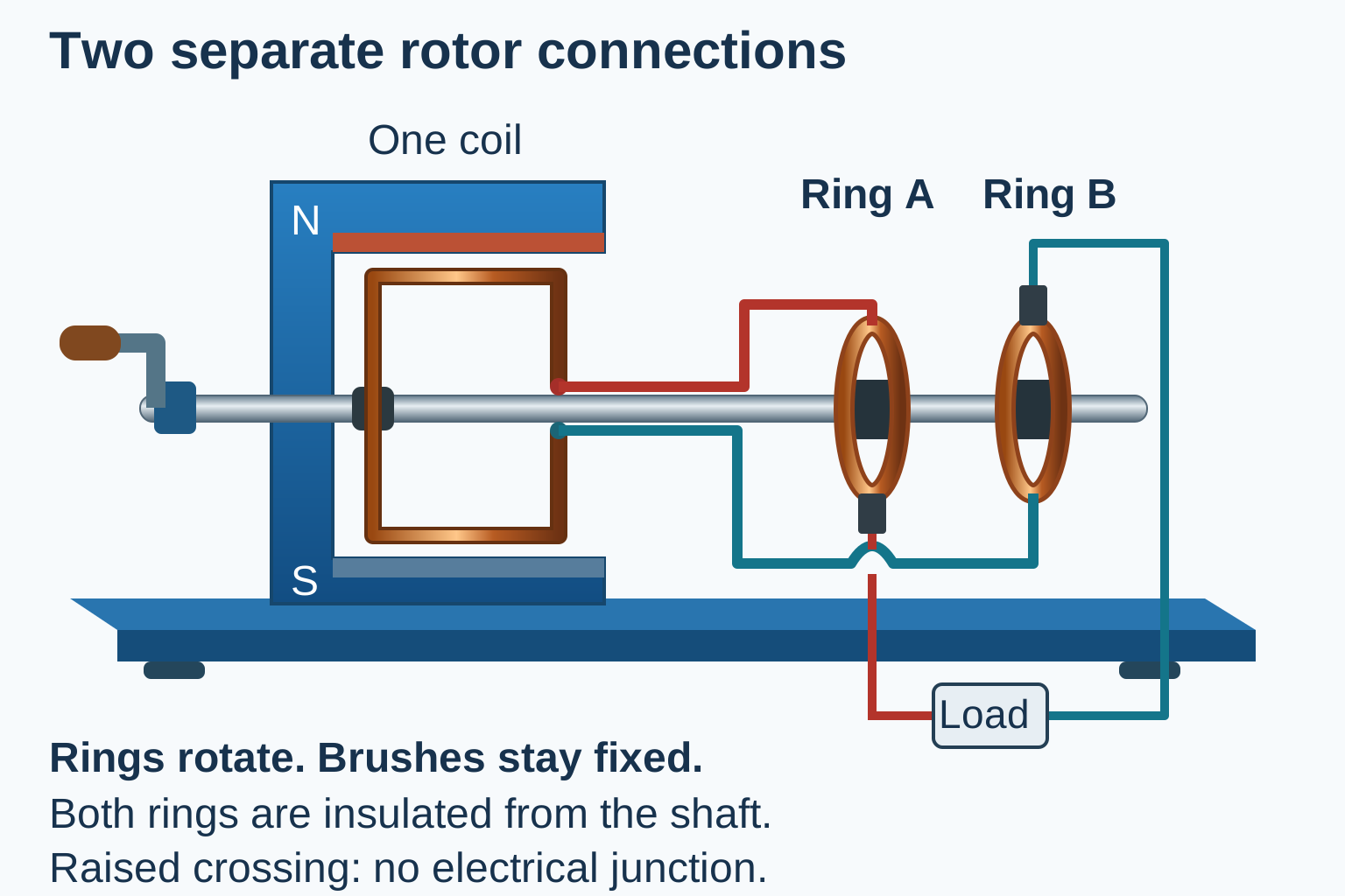
Two separate rotor connections

One coil has separate red and teal leads to ring A and ring B; one brush on each ring connects to opposite load terminals. An arched crossing has no junction.Each end of the rotating coil connects to its own continuous slip ring. Two stationary brushes complete the circuit through the load; the shaft and crossing conductors remain electrically separate.Open full diagram

Flux and emf are a quarter-cycle apart
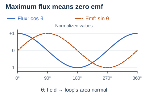
Solid cosine flux curve and dashed sine emf curve over one full turn; flux extrema coincide with zero emf.For uniform rotation, per-turn flux is BA cos θ and coil emf is NBAω sin θ, with θ measured between the field and the area normal. At maximum flux, emf is zero; at zero flux, emf magnitude is largest.Open full diagram

Example 3: Pulling a Loop

\(\vec{B}\) (into page) × × × × × × × × × \(v\) \(L\) → \(x\)

Real-World Applications

Generators
Rotating coils in magnetic fields produce AC electricity for power grids worldwide.
Transformers
Changing current in one coil induces EMF in a nearby coil, stepping voltage up or down.
Induction Cooktops
Rapidly alternating fields induce eddy currents in metal cookware, heating it directly.

Ideal transformer model

In this separate ideal closed-circuit model, changing magnetic flux couples the coils and no charge crosses between circuits.

A transformer has 200 primary and 100 secondary turns, with 120 V RMS primary input and 60 W secondary load. Find the secondary voltage and both currents.

Show answer and explanation

The secondary voltage is 60 V RMS. In the ideal model the secondary current is 1 A and primary current is 0.5 A.
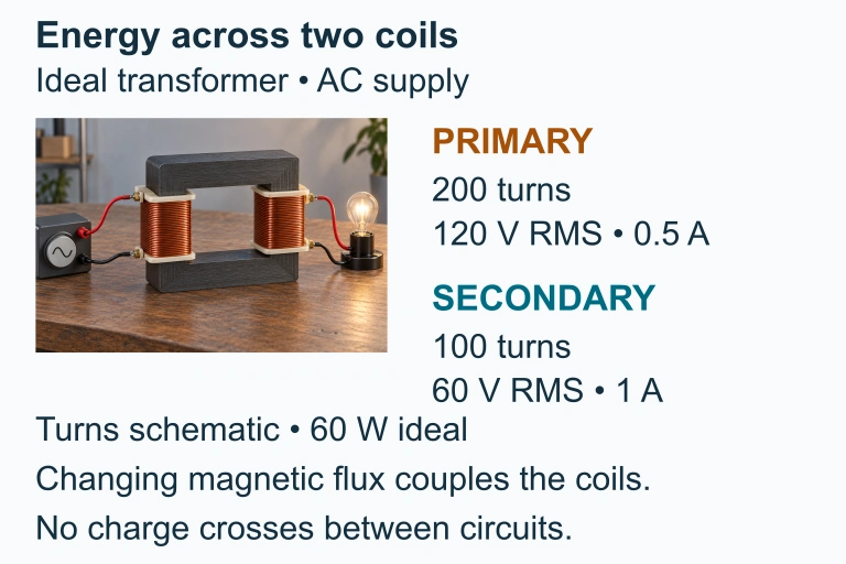
Ideal transformer 200:100 turns, 120→60 V and 0.5→1 A, 60 W conserved; no charge crosses core.
For an ideal 200:100 transformer, 120 V RMS at the primary corresponds to 60 V RMS at the secondary. A 60 W load draws 1 A on the secondary and 0.5 A on the primary.

Motional EMF

When a conducting rod moves through a magnetic field, the free charges inside experience a magnetic force that separates them, creating a potential difference:

\(R\) \(L\) \(v\) \(\vec{B}\) (out of page) \(I\)

Common Mistakes

✕ Forgetting \(N\)
For a coil with multiple turns, the EMF is multiplied by \(N\). Missing this factor gives an answer that is too small.
✕ Ignoring \(\cos\theta\)
If the field is not perpendicular to the loop, you must include the angle factor. \(\theta = 0\) means maximum flux, not zero.
✕ Wrong Lenz Direction
The induced current opposes the change in flux, not the flux itself. If flux is decreasing, the induced field supports it.

Key Formulas Summary

Quantity Formula Units
Magnetic Flux \(\Phi_B = BA\cos\theta\) Wb (Weber)
Faraday's Law \(\mathcal{E} = -N\,\dfrac{d\Phi_B}{dt}\) V (Volts)
Motional EMF \(\mathcal{E} = BLv\) V (Volts)
Peak EMF (Generator) \(\mathcal{E}_{\max} = NBA\omega\) V (Volts)
Induced Current \(I = \dfrac{|\mathcal{E}|}{R}\) A (Amperes)

Question 1 of 5

A magnetic field through a loop doubles in \(0.5\) s. If the initial flux is \(0.02\) Wb, what is the magnitude of the induced EMF?

Question 2 of 5

According to Lenz's Law, if the magnetic flux through a loop is decreasing, the induced current will:

Question 3 of 5

A rod of length \(L = 0.50\) m moves at \(v = 4.0\) m/s perpendicular to a field of \(B = 0.80\) T. What is the motional EMF?

Question 4 of 5

A coil with \(N = 100\) turns has an area of \(0.02\) m². The field through it changes from \(0.5\) T to \(0\) T in \(0.1\) s. What is the induced EMF?

Question 5 of 5

A flat loop lies in a plane parallel to a uniform magnetic field. What is the magnetic flux through the loop?