
SECTION 1
Historical Context & Motivation
The study of wave interference traces its origins to a fundamental debate that consumed physicists for centuries: is light a stream of particles or a wave? While Isaac Newton championed a corpuscular theory in the late 1600s, several European natural philosophers suspected that wave-like behavior could explain phenomena that particles alone could not. The decisive evidence arrived in the early nineteenth century when Thomas Young demonstrated that two beams of light could combine to produce alternating bright and dark fringes—a pattern explicable only if light behaved as a wave capable of constructive and destructive interference. This single experiment redirected the course of physics and laid the groundwork for our modern understanding of superposition, standing waves, and physical optics.
1678 • Huygens' Wave Theory
1801 • Young's Double-Slit Experiment
1821 • Fresnel's Mathematical Framework
1864 • Maxwell's Electromagnetic Theory
The concept of interference extends far beyond light. Sound waves in concert halls, water waves in harbors, and even quantum probability waves all obey the same superposition principle. The central question this lesson addresses is: What happens when two or more waves occupy the same region of space, and under what conditions do they produce stable, predictable patterns? Answering this question leads us to the principle of superposition, the conditions for constructive and destructive interference, and the elegant physics of standing waves.
SECTION 2
Core Principles & Definitions
Wave interference rests on a single foundational idea: the principle of superposition. When two or more waves pass through the same point in space, the resultant displacement at that point equals the algebraic sum of the individual displacements. This principle holds for all linear waves—mechanical waves on strings, sound pressure waves in air, and electromagnetic waves in vacuum. It is the engine behind every interference and standing-wave phenomenon you will encounter on the AP Physics 2 exam.
Superposition Principle
Constructive Interference
Destructive Interference
Standing Waves
Coherence
KEY TAKEAWAY
SECTION 3
Visualizing Interference
The diagram above illustrates the two extreme cases of two-source interference for waves of equal amplitude. In the left panel, the cyan wave y₁ and the violet wave y₂ are perfectly in phase: every crest of y₁ coincides with a crest of y₂, and the resultant (green) has double the amplitude. In the right panel, y₂ is shifted by exactly half a wavelength so that every crest of y₁ aligns with a trough of y₂, and the resultant is a flat line—total cancellation. Real-world scenarios typically fall between these extremes, producing a resultant amplitude anywhere from zero to 2A depending on the phase difference between the overlapping waves.
SECTION 4
Mathematical Framework
The quantitative treatment of interference centers on the path-length difference (Δℓ) between two waves arriving at the same observation point. Because each full wavelength λ corresponds to a 2π radian phase shift, the path-length difference determines whether the waves reinforce, cancel, or produce some intermediate amplitude.
CONSTRUCTIVE INTERFERENCE CONDITION
Δℓ = path-length difference between two sources and the observation point; λ = wavelength; n = order number (integer). When Δℓ is a whole number of wavelengths, crests align with crests and the waves add.
DESTRUCTIVE INTERFERENCE CONDITION
When the path-length difference equals a half-integer number of wavelengths, crests align with troughs and the waves cancel.
STANDING WAVE — STRING FIXED AT BOTH ENDS
fₙ = frequency of the n-th harmonic; v = wave speed on the string; L = length of the string; n = harmonic number. The fundamental (first harmonic) corresponds to n = 1, with λ₁ = 2L.
STANDING WAVE — OPEN-OPEN OR CLOSED-CLOSED PIPE
An open-open pipe supports all harmonics, identical in form to a string fixed at both ends. Here v is the speed of sound in the medium and L is the pipe length. Both ends are antinodes.
STANDING WAVE — OPEN-CLOSED PIPE
A pipe open at one end and closed at the other supports only odd harmonics. The closed end is a displacement node and the open end is an antinode, so the fundamental wavelength is λ₁ = 4L.
AP Exam Tip
SECTION 5
Standing Waves in Detail
A standing wave forms when two identical traveling waves move in opposite directions through the same medium. Rather than propagating energy in one direction, the resultant pattern oscillates in place, with certain points—called nodes—that remain permanently at rest, and points midway between them—called antinodes—that oscillate with maximum amplitude. On a guitar string fixed at both ends, boundary conditions require nodes at each fixed point, restricting the string to vibrate at discrete resonant frequencies (harmonics). This quantization of allowed frequencies is what gives each instrument its characteristic timbre.
| Boundary Condition | Allowed Harmonics | Wavelength Formula | Frequency Formula |
|---|---|---|---|
| String fixed at both ends | All: n = 1, 2, 3, … | λₙ = 2L / n | fₙ = nv / 2L |
| Open-open pipe | All: n = 1, 2, 3, … | λₙ = 2L / n | fₙ = nv / 2L |
| Open-closed pipe | Odd only: n = 1, 3, 5, … | λₙ = 4L / n | fₙ = nv / 4L |
Summary of standing wave formulas by boundary condition
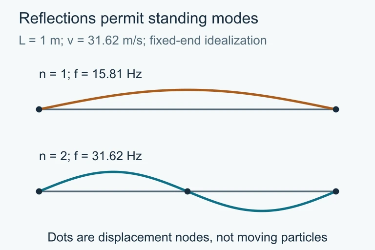 Fixed-end ideal standing modes; nodes mark zero displacement.
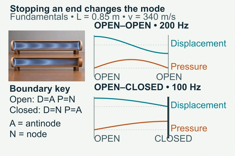 Fundamental displacement and pressure amplitude profiles for ideal equal-length open and stopped pipes. D means displacement, P means pressure, A antinode and N node; vertical height is normalized amplitude, not sideways air motion.
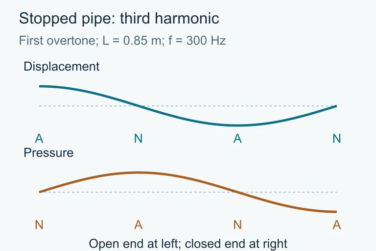 For an open–closed pipe, the first overtone is the third harmonic: f3 = 3v/(4L) = 300 Hz for v = 340 m/s and L = 0.85 m. Displacement and pressure nodes are complementary; the pipe is open left and closed right.
 Successive resonances of the air column differ in length by half a wavelength. Comparing the two lengths cancels a common open-end correction when the tube geometry stays fixed.
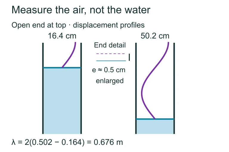 Resonance lengths 16.4 cm and 50.2 cm differ by half a wavelength, giving λ = 0.676 m. At 512 Hz, the sound speed is about 346.1 m/s; the common end correction is about 0.5 cm.
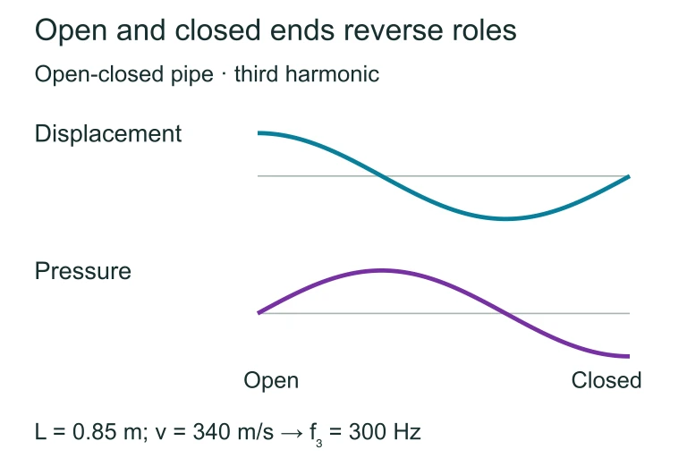 In an open–closed pipe, displacement has an antinode at the open end and a node at the closed end; pressure reverses those roles. For L = 0.85 m and v = 340 m/s, the third harmonic is 300 Hz.
SECTION 6
Worked Example
Finding the Third Harmonic of an Open-Closed Pipe
- 1
Step 1 — Identify Given Values
An organ pipe is open at one end and closed at the other. Its length is L = 0.85 m. The speed of sound in the concert hall air is v = 340 m/s. We want the frequency of the third harmonic. - 2
Step 2 — Determine Applicable Formula
For an open-closed pipe, only odd harmonics are present. The harmonic numbers are n = 1, 3, 5, … The frequency of the n-th harmonic is fₙ = nv / (4L). The third harmonic corresponds to n = 3 (this is the first overtone). - 3
Step 3 — Substitute and Solve
f₃ = 3 × (340 m/s) / (4 × 0.85 m) = 1020 / 3.40 = 300 Hz.f₃ = 300 Hz - 4
Step 4 — Find the Wavelength
λ₃ = 4L / n = 4(0.85) / 3 = 3.40 / 3 ≈ 1.13 m. We can verify: v = f₃ × λ₃ = 300 × 1.13 = 340 m/s ✓.λ₃ ≈ 1.13 m - 5
Step 5 — Interpret Physically
The third harmonic of this pipe is three times the fundamental frequency (f₁ = 100 Hz). Note that f₂ = 200 Hz does not exist for this pipe because even harmonics are not supported by the open-closed boundary condition. The next harmonic above the fundamental is the third, not the second.
SECTION 7
Comparing Interference Scenarios
Interference manifests differently depending on whether the waves are transverse or longitudinal, whether the medium is bounded, and whether the sources are coherent. The table below summarizes key comparisons that frequently appear on the AP Physics 2 exam. Understanding these distinctions will help you select the correct model when analyzing a given physical scenario.
| Feature | Traveling Wave Interference | Standing Waves |
|---|---|---|
| Energy transport | Energy propagates in the direction of wave travel | No net energy transport; energy oscillates between KE and PE |
| Amplitude pattern | Varies continuously in space; depends on path-length difference | Fixed nodes (zero amplitude) and antinodes (maximum amplitude) |
| Requires boundaries? | No—two coherent sources in open space suffice | Yes—reflections at boundaries create counter-propagating waves |
| Frequency constraint | Any two coherent frequencies (same f) produce stable pattern | Only resonant frequencies (harmonics) satisfy boundary conditions |
| Examples | Double-slit experiment, noise-canceling headphones, radio signal fading | Guitar strings, organ pipes, laser cavities, microwave ovens |
KEY TAKEAWAY
SECTION 8
Connections to Advanced Topics
The principles of superposition and standing waves extend well beyond classical mechanics and AP Physics 2. In quantum mechanics, the allowed energy states of a particle confined in a potential well are analogous to the resonant modes of a vibrating string: only certain quantized wavelengths (and hence energies) satisfy the boundary conditions imposed by the well. The mathematics is strikingly similar—de Broglie wavelengths replace mechanical wavelengths, and probability amplitudes replace displacement amplitudes. Additionally, thin-film interference and diffraction gratings, which you may encounter later in AP Physics 2, are direct applications of the path-length-difference framework introduced in this lesson.
| AP Physics 2 Concept | Advanced Extension |
|---|---|
| Standing waves on a string (fₙ = nv/2L) | Particle in a 1-D box: Eₙ = n²h²/(8mL²) — same boundary-condition logic |
| Path-length difference for two-source interference | Thin-film interference, diffraction gratings, Michelson interferometry |
| Nodes and antinodes in pressure standing waves | Acoustic resonance in musical instruments, Chladni patterns, ultrasound imaging |
| Superposition of mechanical waves | Fourier analysis: any periodic wave as a sum of sinusoidal harmonics |
For the AP Physics 2 exam, you are not expected to solve quantum-mechanical problems, but understanding that standing-wave boundary conditions lead to quantization gives you a powerful conceptual bridge to modern physics topics tested in Unit 7 (Quantum, Atomic, and Nuclear Physics). Recognizing that interference is universal—applying to sound, light, matter waves, and beyond—strengthens your ability to transfer reasoning across contexts, which is precisely what the exam's qualitative-quantitative translation and representation-translation FRQs demand.
SECTION 9
Practice Problems
Question 1: CONCEPTUAL
- A. Constructive interference — a loud maximum
- B. Destructive interference — a quiet minimum
- C. No interference — the waves pass through each other without interacting
- D. A beat frequency equal to 1.5 times the original frequency
Show answer (B)
Question 2: BASIC CALCULATION
- A. 100 Hz
- B. 200 Hz
- C. 400 Hz
- D. 576 Hz
Show answer (B)
Question 3: INTERMEDIATE
- A. 256 Hz
- B. 262 Hz
- C. 267 Hz
- D. 343 Hz
Show answer (C)
Question 4: APPLIED
4 ptsShow answer
Question 5: CRITICAL THINKING
4 ptsShow answer
SUMMARY
Lesson Summary
Summary
Wave interference arises from the principle of superposition: the net displacement at any point is the algebraic sum of all individual wave displacements. When two coherent waves overlap, constructive interference occurs at locations where the path-length difference is a whole-number multiple of the wavelength (Δℓ = nλ), and destructive interference occurs where Δℓ = (n + ½)λ.
Standing waves are the special interference pattern formed by two identical waves traveling in opposite directions, producing fixed nodes and antinodes. The boundary conditions determine which harmonics are allowed: strings fixed at both ends and open-open pipes support all harmonics (fₙ = nv/2L), while open-closed pipes support only odd harmonics (fₙ = nv/4L, n = 1, 3, 5, …). Mastery of these relationships—and the ability to translate between graphical, verbal, and mathematical representations—is essential for success on the AP Physics 2 exam.