

AP Physics 2 • Waves, Sound, and Physical Optics

Thin-Film Interference

How nanometer-thick films produce the vivid colors seen in soap bubbles, oil slicks, and optical coatings.

An atom with wave and electric energy symbols.
Inside this lesson 10 sections 5 questions 9 figures

SECTION 1

Historical Context & Motivation

The shimmering colors of a soap bubble captivated natural philosophers for centuries, yet explaining why a transparent film of water could produce vivid hues required a radical shift in how scientists understood light. The phenomenon of thin-film interference sits at the crossroads of wave optics and materials science, connecting the wave nature of light to measurable film thicknesses on the order of hundreds of nanometers. Understanding thin-film interference was pivotal in establishing the wave model of light and continues to underpin modern technologies ranging from anti-reflective eyeglass coatings to semiconductor fabrication. On the AP Physics 2 exam, this topic weaves together principles of superposition, phase shifts, and the behavior of light at boundaries—skills that recur throughout physical optics.

1665 • Newton's Rings

Robert Hooke observes colored rings in thin air gaps between glass surfaces. Isaac Newton later studies these Newton's rings systematically, though he interprets them through a corpuscular theory of light.

1801 • Young's Double-Slit Experiment

Thomas Young demonstrates that light produces an interference pattern, providing the first compelling evidence for the wave nature of light and setting the theoretical foundation for understanding thin-film colors.

1816 • Fresnel's Wave Theory

Augustin-Jean Fresnel develops a rigorous mathematical framework for diffraction and interference, enabling quantitative predictions of thin-film color patterns based on film thickness and refractive index.

1935 • Anti-Reflective Coatings

Alexander Smakula at Zeiss patents the first practical single-layer anti-reflective coating for camera lenses, applying thin-film interference to eliminate unwanted reflections and dramatically improving optical performance.

The central question that thin-film interference answers is deceptively simple: why does a transparent film—one that transmits nearly all incident light—selectively reflect certain wavelengths and not others? The answer lies in the constructive and destructive superposition of light waves reflected from the film's top and bottom surfaces, with the outcome depending critically on the film's thickness, the refractive indices involved, and the wavelength of the incident light.

SECTION 2

Core Principles & Definitions

Thin-film interference arises whenever light encounters a layer of material whose thickness is comparable to the wavelength of visible light—typically on the order of 100–1000 nm. Two reflected waves emerge from such a film: one from the top surface and one from the bottom surface. Whether these waves reinforce or cancel each other depends on their path-length difference and on any phase shifts that occur upon reflection. Understanding thin-film interference therefore requires mastering four foundational ideas.

1

Reflection Phase Shift

When light reflects off a medium with a higher refractive index (low-to-high boundary), the reflected wave undergoes a phase shift of half a wavelength (λ/2), equivalent to 180°. Reflection from a lower-index medium produces no phase shift.
2

Optical Path Length

Inside the film, light travels at a reduced speed v = c/n. The optical path length through a film of thickness t and refractive index n is 2nt for normal incidence, since the wave traverses the film twice (down and back up).
3

Superposition Condition

Constructive interference occurs when the total phase difference between the two reflected waves is an integer multiple of the wavelength. Destructive interference occurs when it is a half-integer multiple. The total phase difference accounts for both the optical path and any reflection phase shifts.
4

Wavelength Dependence

Because the interference condition depends on wavelength, a film of fixed thickness will constructively reflect some colors while destructively canceling others. This wavelength selectivity is what produces the characteristic iridescent colors of thin films.
✦

KEY TAKEAWAY

Think of thin-film interference like two runners on a track. Runner A (wave reflected from the top surface) and Runner B (wave reflected from the bottom surface) start at nearly the same point, but Runner B takes a detour through the film's interior and may also receive a "push" (phase shift) at a boundary. When both runners arrive at the finish line exactly in step, you get a bright reflection (constructive interference). When one arrives half a stride behind the other, they cancel out (destructive interference). The thickness of the film controls how long Runner B's detour is, and therefore which colors survive.

SECTION 3

Visual Explanation

Thin-Film Interference — Normal Incidencen₁ (air) = 1.00n₂ (film)n₃ (substrate)tIncident rayRay 1(reflected at top)Ray 2(reflected at bottom)THIN FILM (n₂)Substrate (n₃)Air (n₁)Ray 1: may gain λ/2 phase shift if n₂ > n₁Ray 2: travels extra optical path 2n₂t; may gain λ/2 shift if n₃ > n₂Interference outcome depends on total phase difference between Ray 1 and Ray 2
The incident ray strikes the thin film and produces two reflected rays. Ray 1 reflects from the top surface (air–film boundary), while Ray 2 penetrates the film, reflects off the bottom surface (film–substrate boundary), and exits through the top. Ray 2 travels an extra optical path length of 2n₂t. Each reflection at a low-to-high index boundary introduces a λ/2 phase shift.

In the diagram above, notice that the two reflected rays emerge from nearly the same location (for near-normal incidence) and can therefore interfere with each other in the far field. The crucial physics involves two separate contributions to the total phase difference. First, Ray 2 accumulates an additional optical path length of 2n₂t from its round trip through the film. Second, each reflection must be examined for a possible half-wavelength phase shift. If one reflection inverts the wave but the other does not, the reflections contribute a net phase difference of λ/2, which changes the condition for constructive versus destructive interference. Conversely, if both reflections invert (or neither does), the reflection phase shifts cancel and only the optical path length matters.

SECTION 4

Mathematical Framework

The interference conditions for thin films depend on the number of phase-inverting reflections. We distinguish two cases based on whether the two reflected rays experience an unequal or equal number of half-wavelength phase shifts.

Case 1: One Phase-Inverting Reflection (e.g., n₁ < n₂ > n₃)

When only one of the two reflections occurs at a low-to-high index boundary, the reflected rays start with a net phase difference of λ/2. To achieve constructive interference, the optical path difference must compensate for this half-wavelength offset. A common example is a soap film (n₂ ≈ 1.33) in air (n₁ = n₃ = 1.00): the top reflection (air→film) is phase-inverted, but the bottom reflection (film→air) is not.

CONSTRUCTIVE (ONE INVERSION)

2n2t=(m+½)λ,m=0,1,2,…2n₂t = (m + ½)λ, m = 0, 1, 2, …

n₂ = refractive index of the film, t = film thickness, λ = wavelength of light in vacuum/air, m = order number (non-negative integer).

DESTRUCTIVE (ONE INVERSION)

2n2t=mλ,m=0,1,2,…2n₂t = mλ, m = 0, 1, 2, …

When the optical path difference equals a whole number of wavelengths, it aligns with the half-wave offset from the reflection, producing cancellation.

Case 2: Zero or Two Phase-Inverting Reflections (e.g., n₁ < n₂ < n₃)

When both reflections are phase-inverted (both boundaries go from low to high index) or neither is, the two half-wavelength shifts cancel, and there is no net reflection phase difference. The conditions for constructive and destructive interference are the standard ones. A common example is an anti-reflective coating (e.g., MgF₂, n₂ ≈ 1.38) on glass (n₃ ≈ 1.52) in air (n₁ = 1.00): both the air→coating and the coating→glass reflections are phase-inverted.

CONSTRUCTIVE (ZERO OR TWO INVERSIONS)

2n2t=mλ,m=1,2,3,…2n₂t = mλ, m = 1, 2, 3, …

The optical path difference must be a whole number of wavelengths so the two reflected waves arrive in phase.

DESTRUCTIVE (ZERO OR TWO INVERSIONS)

2n2t=(m+½)λ,m=0,1,2,…2n₂t = (m + ½)λ, m = 0, 1, 2, …

A half-wavelength mismatch in path length now produces destructive interference. This is the principle behind anti-reflective coatings, which are designed to satisfy this condition for a target wavelength.

💡

AP EXAM TIP

Before plugging into a formula, always determine how many phase inversions occur by comparing the refractive indices at each boundary. A common error is to apply the wrong case because students forget to check the bottom reflection. Draw a quick sketch labeling n₁, n₂, and n₃ and mark each inverted reflection with a small "π" symbol.

SECTION 5

Detailed Breakdown — Real-World Applications

Thin-film interference is not merely a laboratory curiosity—it underlies several technologies and natural phenomena that you encounter daily. The diagram below illustrates how an anti-reflective (AR) coating on glass works by engineering destructive interference for reflected light, thereby maximizing transmission.

Anti-Reflective Coating — Destructive Interference of Reflected Lightn₁ = 1.00 (air)MgF₂ Coating (n₂ = 1.38)Glass (n₃ = 1.52)tIncidentRay 1 (inverted)Ray 2 (inverted)Both reflections arelow → high: 2 inversionsCommon Thin-Film Examples● Anti-Reflective Coatingn₁ < n₂ < n₃ → two inversions → destructive at 2n₂t = (m+½)λ● Soap Bubble in Airn₁ < n₂ > n₃ → one inversion → constructive at 2n₂t = (m+½)λ
An anti-reflective MgF₂ coating on glass illustrates Case 2: both reflections occur at low-to-high index boundaries, so both rays are phase-inverted. The two inversions cancel, and destructive interference of reflected light occurs when 2n₂t = (m + ½)λ. For minimum thickness, set m = 0, giving t = λ / (4n₂).
ApplicationRefractive Index ArrangementDesign Goal
Anti-reflective coatingn₁ < n₂ < n₃ (e.g., air–MgF₂–glass)Destructive interference for reflected light → maximize transmission
Soap bubblen₁ < n₂ > n₃ (air–soap–air)Selective constructive reflection → colorful iridescence
Oil slick on watern₁ < n₂ < n₃ (air–oil–water, typically)Variable thickness → rainbow of colors across the slick
Dielectric mirrorAlternating high/low n layersConstructive interference for reflected light → reflectivity > 99%

Common thin-film applications and their refractive index configurations
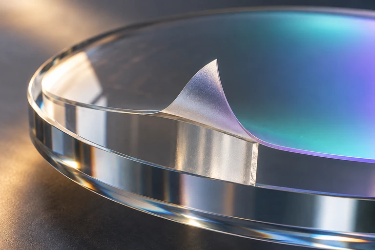
Single glass substrate and an explicitly exaggerated lifted coating layer are visible; generated tint is qualitative and cannot predict spectral reflectance. Separate exact panel: Computed reflectance versus vacuum wavelength has a nonzero minimum near550nm for a99.6nm MgF2 coating on glass.At normal incidence, both reflections in this air–MgF₂–glass film undergo a phase inversion. A quarter-wave optical thickness minimizes reflection near the design wavelength; incomplete amplitude matching leaves a nonzero minimum.
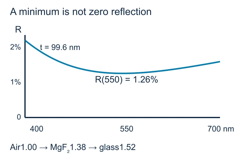
Quarter-wave phase cancellation requires amplitude matching for zero design-wavelength reflection.. At normal incidence, both reflections in this air–MgF₂–glass film undergo a phase inversion. A quarter-wave optical thickness minimizes reflection near the design wavelength; incomplete amplitude matching leaves a nonzero minimum.At normal incidence, both reflections in this air–MgF₂–glass film undergo a phase inversion. A quarter-wave optical thickness minimizes reflection near the design wavelength; incomplete amplitude matching leaves a nonzero minimum.

SECTION 6

Worked Example

Minimum Thickness of an Anti-Reflective Coating

  1. 1

    Step 1 — Identify Given Values and Configuration

    A camera lens (n₃ = 1.52) is coated with a thin layer of MgF₂ (n₂ = 1.38) to minimize reflection of green light at λ = 550 nm. The surrounding medium is air (n₁ = 1.00). Since n₁ < n₂ < n₃, both reflections are phase-inverting (low-to-high transitions at both boundaries), so we are in Case 2 (zero or two inversions).
  2. 2

    Step 2 — Select the Appropriate Condition

    We want to minimize reflection, which means destructive interference of the reflected light. For Case 2, destructive interference occurs when 2n₂t = (m + ½)λ. To find the minimum thickness, we set m = 0.
  3. 3

    Step 3 — Solve for Minimum Thickness

    Setting m = 0: 2n₂t = (0 + ½)λ = λ/2. Solving for t: t = λ / (4n₂) = 550 nm / (4 × 1.38) = 550 / 5.52 ≈ 99.6 nm.
    t ≈ 99.6 nm
  4. 4

    Step 4 — Interpret the Result

    A coating roughly 100 nm thick eliminates reflection of 550 nm green light. This is approximately one-quarter of the wavelength of light inside the film (λ/n₂ = 550/1.38 ≈ 399 nm; one quarter of that is ≈ 100 nm). This is why anti-reflective coatings are often called quarter-wave coatings. The coating will still partially reflect other wavelengths, which is why coated lenses often have a slight purple or green tint.

SECTION 7

Common Pitfalls & Clarifications

PitfallWhy It HappensCorrect Approach
Forgetting to check both reflections for phase inversionsStudents focus only on the top surface and assume all problems are Case 1Always list n₁, n₂, and n₃ and compare at each boundary. Two low-to-high reflections means Case 2.
Using the wavelength in the film instead of in vacuumThe equations 2n₂t = … already account for the refractive index, so λ refers to the free-space wavelengthUse λ as the vacuum (or air) wavelength. The factor n₂ in 2n₂t converts the physical path to an optical path.
Confusing "minimize reflection" with "maximize reflection"Students apply constructive conditions when they want to eliminate reflections"Minimize reflection" = destructive interference of reflected light. "Maximize reflection" = constructive interference of reflected light.
Using m = 1 for minimum thickness instead of m = 0Confusion between order numbering conventionsMinimum non-zero thickness corresponds to m = 0 in the (m + ½)λ condition or m = 1 in the mλ condition. Either way, choose the smallest m that gives t > 0.

Frequently encountered errors on thin-film interference problems

⚡

REFLECTION PHASE SHIFT RULE

The phase-shift rule for light is analogous to wave reflections on strings. A light wave reflecting from a higher-index medium is like a pulse on a rope hitting a rigid wall—it inverts. Reflecting from a lower-index medium is like a pulse reaching a free end—it reflects without inversion. On the AP exam, always think: "higher index = fixed end = inversion; lower index = free end = no inversion." This mechanical analogy makes the rule easy to remember under time pressure.

SECTION 8

Connections to Broader Wave Optics

Thin-film interference is one member of a family of wave-optics phenomena—all governed by the superposition principle but differing in geometry and application. The table below situates thin-film interference alongside other interference and diffraction effects you may encounter on the AP Physics 2 exam or in more advanced coursework.

PhenomenonGeometryKey ConditionOn AP Physics 2?
Thin-film interferenceTwo reflections from parallel film surfaces2n₂t = (m + ½)λ or mλYes
Double-slit (Young's)Two coherent point sources separated by distance dd sin θ = mλ (constructive)Yes
Single-slit diffractionInfinite point sources across a slit of width aa sin θ = mλ (minima)Yes
Diffraction gratingN parallel slits separated by dd sin θ = mλ (sharp maxima)Yes
Multilayer dielectric mirrorMany alternating thin filmsBragg-like condition for each layerNo (beyond AP 2 scope)

Thin-film interference in the context of other wave-optics phenomena

In more advanced physics courses, thin-film interference generalizes to multilayer systems where dozens of alternating high- and low-index films produce nearly perfect mirrors for specific wavelengths—a technology essential to laser cavities, fiber-optic telecommunications, and gravitational-wave detectors like LIGO. The fundamental principle remains identical: controlling the optical path length and reflection phase shifts at every boundary to engineer constructive or destructive interference with extreme precision.

SECTION 9

Practice Problems

Question 1: CONCEPTUAL

A thin film of oil (n = 1.45) floats on water (n = 1.33). White light is incident from air (n = 1.00). At the top surface of the oil, the reflected wave undergoes a phase inversion. At the bottom surface (oil–water), does the reflected wave undergo a phase inversion?
  • A. Yes, because the wave travels from oil into water, which has a higher refractive index.
  • B. Yes, because all reflections produce a phase inversion.
  • C. No, because the wave travels from oil (n = 1.45) into water (n = 1.33), which has a lower refractive index.
  • D. No, because phase inversions only occur at the first surface a wave encounters.
Show answer (C)
The correct answer is C. A phase inversion occurs only when light reflects off a medium with a higher refractive index (low-to-high boundary). At the oil–water boundary, the oil (n = 1.45) has a higher index than water (n = 1.33), so this is a high-to-low boundary—no inversion occurs. Choice A is wrong because it incorrectly states water has a higher index than oil. Choice B is wrong because phase inversions do not occur at every reflection—only at low-to-high boundaries. Choice D is wrong because phase inversions can occur at any surface, not just the first one; what matters is the relative indices at that boundary.

Question 2: BASIC CALCULATION

A soap film (n = 1.33) in air appears bright green (λ = 530 nm) at its thinnest point that gives first-order constructive interference. What is the minimum film thickness? (Note: air–soap–air → one phase-inverting reflection.)
  • A. 99.6 nm
  • B. 199.2 nm
  • C. 265 nm
  • D. 398 nm
Show answer (A)
The correct answer is A. For a soap film in air (Case 1: one phase-inverting reflection), constructive interference requires 2n₂t = (m + ½)λ. The minimum thickness occurs at m = 0: 2(1.33)t = (½)(530 nm), so t = 530/(4 × 1.33) = 530/5.32 ≈ 99.6 nm. Choice B (199.2 nm) corresponds to m = 1 in the half-wavelength case, which is not the minimum. Choice C (265 nm) results from forgetting to include the refractive index (530/2). Choice D (398 nm) results from using the wrong formula (dividing by n instead of 4n).

Question 3: INTERMEDIATE

A thin coating of material (n₂ = 1.25) is applied to a glass lens (n₃ = 1.50) to create an anti-reflective coating for light of wavelength 500 nm. Since n₁ < n₂ < n₃, both reflections are phase-inverting. What is the minimum coating thickness for destructive interference of the reflected light?
  • A. 100 nm
  • B. 125 nm
  • C. 200 nm
  • D. 250 nm
Show answer (A)
The correct answer is A. With two phase-inverting reflections (Case 2), the inversions cancel and destructive interference requires 2n₂t = (m + ½)λ. Setting m = 0 for minimum thickness: 2(1.25)t = (½)(500), giving 2.50t = 250, so t = 100 nm. This is a quarter-wave coating: t = λ/(4n₂) = 500/(4 × 1.25) = 100 nm. Choice B (125 nm) comes from dividing λ by 4 without including n₂. Choice C (200 nm) uses the constructive condition mλ with m = 1 incorrectly. Choice D (250 nm) simply halves the wavelength without accounting for the refractive index.

Question 4: APPLIED

5 pts
A student designs an experiment to measure the refractive index of a thin transparent film. She places the film on a dense flint glass slide and illuminates it with monochromatic light of wavelength λ = 600 nm at normal incidence. She observes that the reflected light is at a minimum (destructive interference) when the film thickness is measured (by an independent method) to be 225 nm. The glass has n₃ = 2.40 and air has n₁ = 1.00. (a) Determine the refractive index of the film. Clearly identify how many phase inversions occur and which interference condition (constructive or destructive) you are using. (b) Describe how the student could verify her result by changing the wavelength of light and predicting the next wavelength that produces a reflection minimum for the same film thickness. (c) If the film thickness were doubled to 450 nm, would 600 nm light still be at a destructive minimum? Justify your answer. (d) Explain one source of systematic error that could affect the accuracy of the measured refractive index.
Show answer
Rubric (5 points): (a) [1 point] Identify the phase inversion situation. Since n₁ = 1.00 < n₂ (unknown) < n₃ = 2.40, light reflects from a low-to-high interface at both the top surface (air→film) and the bottom surface (film→glass). Both reflections undergo a phase inversion, giving two total inversions (equivalent to zero net phase difference from reflections). For two inversions, the destructive interference condition is: 2n₂t = (m + ½)λ. Using m = 0 (thinnest film condition): 2n₂(225) = (½)(600) → 450n₂ = 300 → n₂ = 0.667 — this is less than 1.00 (unphysical). Using m = 1: 2n₂(225) = (1.5)(600) → 450n₂ = 900 → n₂ = 2.00. Since 1.00 < 2.00 < 2.40, this is consistent with the two-inversion case. Therefore n₂ = 2.00. [1 point] For clear, logical presentation: correctly identifying the two-inversion case before applying the formula, and verifying that the result is consistent (n₁ < n₂ < n₃). (b) [1 point] For the same film (n₂ = 2.00, t = 225 nm), use the destructive condition: 2n₂t = (m + ½)λ → 2(2.00)(225) = (m + ½)λ → 900 = (m + ½)λ. For m = 0: λ = 1800 nm (infrared, not visible). For m = 1: λ = 600 nm (already known). For m = 2: λ = 360 nm (ultraviolet). The student should illuminate the film with 360 nm light and check whether a reflection minimum is observed. If a minimum appears at 360 nm, this confirms n₂ = 2.00. Alternatively, for m = 0, λ = 1800 nm could be checked with an IR detector. (c) [1 point] With t = 450 nm: 2(2.00)(450) = (m + ½)(600) → 1800 = (m + ½)(600) → m + ½ = 3 → m = 2.5. Since m must be a non-negative integer, 600 nm light does NOT satisfy the destructive interference condition at this thickness. Instead, 1800 nm corresponds to an integer m for constructive interference: 2n₂t = mλ → 1800 = m(600) → m = 3 (integer). So at t = 450 nm, 600 nm light is at a constructive maximum (bright reflection), not a destructive minimum. (d) [1 point] Systematic error: The film thickness measurement may be inaccurate if the measurement instrument has a calibration bias, or if the film is not uniform in thickness across its surface. A non-uniform thickness means the destructive interference condition is only satisfied at certain locations on the film, and the measured thickness might not correspond to the actual thickness at the point where the minimum was observed. This would lead to a systematic error in the calculated refractive index, since n₂ is computed directly from the measured thickness.

Question 5: CRITICAL THINKING

5 pts
A thin film of uniform thickness t and refractive index n₂ is suspended in air (so air is on both sides). White light illuminates the film at normal incidence. (a) Explain why very thin films (t → 0) appear dark in reflected light. (b) As the film thickness gradually increases from zero, describe the sequence of colors an observer would see in reflected light, and explain why this sequence eventually becomes less vivid. (c) Two films have the same thickness but different refractive indices (n₂ = 1.3 and n₂ = 1.5). Which film reflects a longer wavelength most strongly at first-order constructive interference? Justify your answer quantitatively. (d) Explain why transmission and reflection are complementary in thin-film interference (i.e., wavelengths strongly reflected are weakly transmitted and vice versa).
Show answer
Rubric (5 points): (a) [1 point] For a soap-film-in-air geometry (n₁ < n₂ > n₃), only the top reflection (air→film) is phase-inverted, giving one inversion. As t → 0, the optical path difference 2n₂t → 0. The only remaining phase difference is the λ/2 inversion at the top surface. Rays 1 and 2 are therefore exactly half a wavelength out of phase for all visible wavelengths, producing destructive interference. The film appears dark. (b) [1 point] As t increases, the first constructive interference occurs at 2n₂t = λ/2 (m = 0). For very thin films this condition is first met by the shortest visible wavelengths (violet/blue), so the film first appears bluish. With further increase, green, yellow, and then red wavelengths reach their first-order constructive maximum. The sequence repeats at higher orders. At higher orders, multiple wavelengths simultaneously satisfy constructive conditions, and the reflected colors overlap and mix, producing increasingly washed-out, pastel hues rather than vivid spectral colors. (c) [1 point] Using 2n₂t = (m + ½)λ with m = 0: λ = 4n₂t. For n₂ = 1.3: λ = 4(1.3)t = 5.2t. For n₂ = 1.5: λ = 4(1.5)t = 6.0t. The film with n₂ = 1.5 reflects a longer wavelength most strongly because the larger refractive index increases the optical path length, requiring a longer wavelength to satisfy the same interference condition. (d) [1 point] Energy conservation requires that the total intensity of light equals the sum of reflected and transmitted intensities (assuming negligible absorption). When reflected waves constructively interfere, more energy is directed into reflection and less is transmitted. When reflected waves destructively interfere, minimal energy is reflected and nearly all is transmitted. This complementarity is a direct consequence of conservation of energy. [1 point] For coherent, well-organized responses that correctly link physical reasoning to mathematical conditions throughout.

SUMMARY

Summary

Summary

Thin-film interference occurs when light reflects from both the top and bottom surfaces of a film whose thickness is on the order of the wavelength of visible light. The two reflected waves superpose, producing constructive interference (bright reflection) for some wavelengths and destructive interference (canceled reflection) for others. The total phase difference between the two waves depends on the optical path length 2n₂t and on the number of reflection phase inversions (each occurring when light reflects from a medium of higher refractive index).

When there is one net phase inversion (e.g., soap bubble in air), constructive reflection satisfies 2n₂t = (m + ½)λ. When there are zero or two net inversions (e.g., anti-reflective coating on glass), constructive reflection satisfies 2n₂t = mλ and destructive requires 2n₂t = (m + ½)λ. The minimum thickness for a quarter-wave coating is t = λ/(4n₂). Always identify n₁, n₂, and n₃ before selecting the correct interference condition—this single step prevents the most common exam errors.

Varsity Tutors • AP Physics 2: Algebra-Based • Thin-Film Interference