

SECTION 1
Historical Context & Motivation
The study of electric circuits grew from centuries of inquiry into the nature of electricity. Early investigators observed static sparks and the attraction of amber to light objects, but a systematic understanding of steady current flow only became possible once chemical batteries could supply a continuous source of charge. The mathematical relationships that govern simple circuits—linking voltage, current, and resistance—were forged through careful experimentation in the early nineteenth century, and they remain the backbone of every electrical system today, from smartphone chargers to hospital defibrillators.
1800 • Volta's Pile
1827 • Ohm's Law Published
1845 • Kirchhoff's Rules
1882 • Edison's DC Power Grid
The central question these pioneers answered is deceptively simple: How does the arrangement of components in a circuit determine the current through each element and the voltage across it? Answering that question requires understanding series and parallel topologies, the conservation laws that constrain charge and energy flow, and the mathematical tools—Ohm's law and Kirchhoff's rules—that translate physical principles into solvable equations.
SECTION 2
Core Principles & Definitions
A simple circuit is any closed conducting path through which charge can flow, driven by a source of electromotive force (emf) such as a battery. The behavior of every simple circuit rests on a handful of foundational ideas that connect the macroscopic quantities of voltage, current, and resistance to the microscopic motion of charge carriers.
Current (I)
Voltage (V)
Resistance (R)
Ohm's Law
Kirchhoff's Rules
SECTION 3
Visual Explanation — Series & Parallel Topologies
The diagram above captures the two fundamental ways to arrange resistors. In a series configuration, there is only one path for charge to follow, so the current I is identical through every element. Ohm's law applied to each resistor gives individual voltage drops V₁ = IR₁, V₂ = IR₂, and V₃ = IR₃, which must sum to the battery emf by Kirchhoff's loop rule. In a parallel configuration, multiple paths exist between the same two nodes, so each branch experiences the full battery voltage. The junction rule then requires the total current entering a node to equal the sum of branch currents, I₁ + I₂. These two patterns form the building blocks for analyzing any circuit, no matter how complex.
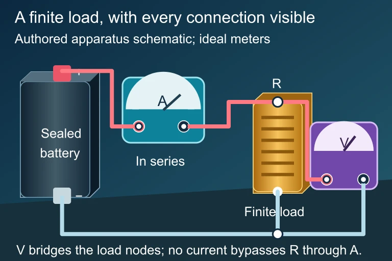 During discharge, internal resistance makes terminal voltage smaller than the emf. The source power divides between useful load power and internal heating.
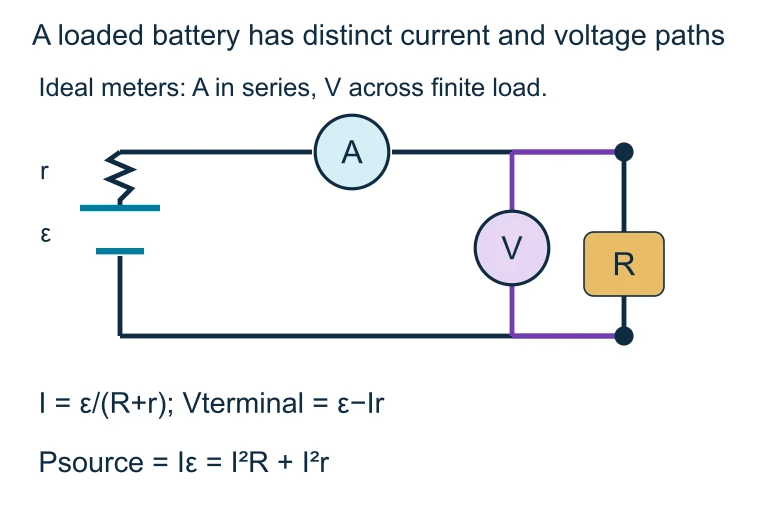 During discharge, internal resistance makes terminal voltage smaller than the emf. The source power divides between useful load power and internal heating.
SECTION 4
Mathematical Framework
OHM'S LAW
V = potential difference across the resistor (V), I = current through the resistor (A), R = resistance (Ω). This is a linear relation valid for ohmic materials.
SERIES EQUIVALENT RESISTANCE
Resistors in series add directly. The equivalent resistance is always larger than the largest individual resistor, so adding series resistors decreases total current.
PARALLEL EQUIVALENT RESISTANCE
The reciprocal of the equivalent resistance equals the sum of the reciprocals of each branch resistance. R_eq is always less than the smallest individual resistor because additional branches provide extra paths for current.
POWER DISSIPATED
P = power dissipated (W). The three equivalent forms follow from substituting Ohm's law. Choose the form that matches the known quantities: P = IV is universal; P = I²R is convenient when current is known; P = V²/R is convenient when voltage is known.
The loop rule (Kirchhoff's voltage law) is a statement of conservation of energy: as you traverse any closed loop, the algebraic sum of all potential gains (from batteries) and drops (across resistors) equals zero. The junction rule (Kirchhoff's current law) is a statement of conservation of charge: current entering a node must equal current leaving it, because charge cannot accumulate in steady state. Together these two rules, combined with Ohm's law, provide enough independent equations to solve for every unknown current and voltage in any resistor network.
SECTION 5
Detailed Breakdown — Combining Series & Parallel
Many real circuits contain combination (series-parallel) networks. The strategy for analyzing them is to simplify from the inside out: identify groups of resistors that are purely in series or purely in parallel, replace each group with its equivalent resistance, and repeat until the entire network reduces to a single equivalent resistor connected to the battery. Once you know the total current from the battery, you can 'unpack' the reductions in reverse order to find the current through and voltage across every individual resistor.
SECTION 6
Worked Example
Worked example
- 1
Step 1 — Identify Given Values
A battery with emf ε = 24 V (assume negligible internal resistance) is connected to R₁ = 8 Ω in series with a parallel combination of R₂ = 12 Ω and R₃ = 6 Ω. We seek the total current, the current through each resistor, and the power dissipated by R₂. - 2
Step 2 — Find the Parallel Equivalent
Apply the parallel resistance formula: 1/R_∥ = 1/R₂ + 1/R₃ = 1/12 + 1/6 = 1/12 + 2/12 = 3/12.R_∥ = 12/3 = 4 Ω - 3
Step 3 — Find Total Equivalent Resistance
R₁ is in series with the parallel combination, so R_eq = R₁ + R_∥ = 8 + 4.R_eq = 12 Ω - 4
Step 4 — Find Total Current
Apply Ohm's law: I_total = ε / R_eq = 24 V / 12 Ω.I_total = 2 A - 5
Step 5 — Find Voltage Across the Parallel Section
The voltage drop across R₁ is V₁ = I_total × R₁ = 2 × 8 = 16 V. By Kirchhoff's loop rule, the voltage across the parallel pair is V_∥ = ε − V₁ = 24 − 16 = 8 V. Equivalently, V_∥ = I_total × R_∥ = 2 × 4 = 8 V, which confirms the result.V_∥ = 8 V - 6
Step 6 — Find Branch Currents
Each parallel branch sees V_∥ = 8 V. Thus I₂ = V_∥ / R₂ = 8/12 ≈ 0.667 A and I₃ = V_∥ / R₃ = 8/6 ≈ 1.333 A. Check: I₂ + I₃ = 0.667 + 1.333 = 2.0 A = I_total. ✓I₂ ≈ 0.67 A, I₃ ≈ 1.33 A - 7
Step 7 — Power Dissipated by R₂
Using P = V²/R is convenient here since we know the voltage across R₂. P₂ = (8)²/12 = 64/12.P₂ ≈ 5.33 W
SECTION 7
Series vs. Parallel — Strengths & Limitations
| Property | Series | Parallel |
|---|---|---|
| Current | Same through all elements | Splits among branches; total = sum of branch currents |
| Voltage | Divides among elements; sum = emf | Same across every branch |
| R_eq | Sum of all resistances (always > largest R) | Reciprocal sum (always < smallest R) |
| Effect of removing one element | Breaks the entire circuit — all current stops | Other branches continue to operate |
| Practical use | Voltage dividers, current-limiting circuits | Household wiring, ensuring independent device operation |
Comparison of series and parallel circuit properties
SECTION 8
Connection to Advanced Circuit Analysis
Simple resistor circuits form the conceptual scaffolding for more complex topics you will encounter in AP Physics 2 and beyond. The same Kirchhoff laws that let you analyze a two-resistor loop also govern circuits containing capacitors (RC circuits), where current is not constant but decays exponentially as the capacitor charges. Internal resistance of real batteries, explored later in the course, adds a series resistor inside the battery itself, causing the terminal voltage to sag under load. Understanding simple DC circuits also prepares you for AC circuit analysis in more advanced courses, where impedance replaces resistance and phasors replace scalar voltages.
| Simple Circuits (This Lesson) | Advanced Extensions |
|---|---|
| Ideal battery with fixed emf ε | Real battery: ε − Ir, where r is internal resistance |
| Resistors only; steady-state DC | RC circuits: time-varying current, exponential charging/discharging |
| Kirchhoff's rules applied to resistor networks | Multi-loop circuits requiring simultaneous equations |
| Power P = IV dissipated as thermal energy | Energy stored in capacitors: U = ½CV² |
How simple circuit concepts extend to advanced topics
On the AP Physics 2 exam, circuit problems frequently ask you to predict what happens when a switch is opened or closed, a resistor is added or removed, or a battery's internal resistance is non-negligible. Mastering the simple circuit principles in this lesson—particularly the conservation-based reasoning encoded in Kirchhoff's rules—gives you the analytical toolkit needed for those more nuanced scenarios.
SECTION 9
Practice Problems
Question 1: CONCEPTUAL
- A. Total current increases; voltage across each resistor increases
- B. Total current increases; voltage across each resistor stays the same
- C. Total current stays the same; voltage across each resistor decreases
- D. Total current decreases; voltage across each resistor stays the same
Show answer (B)
Question 2: BASIC CALCULATION
- A. 2.25 A
- B. 1.5 A
- C. 1.0 A
- D. 0.5 A
Show answer (C)
Question 3: INTERMEDIATE
- A. 10.0 W
- B. 6.67 W
- C. 40.0 W
- D. 20.0 W
Show answer (A)
Question 4: APPLIED
Show answer
Question 5: CRITICAL THINKING
Show answer
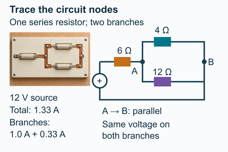 Separate simple-circuit preset: 6 Ω in series with 4 Ω and 12 Ω branches.
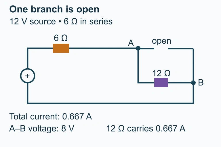 Opening the 4 Ω branch leaves the 12 Ω branch carrying current. A bridge between A and B bypasses both parallel resistors while the 6 Ω series resistor remains.
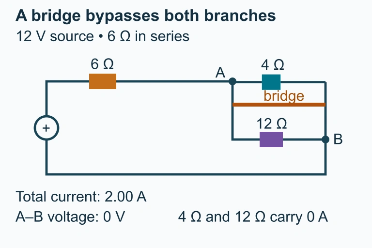 A bridge across nodes A and B bypasses both parallel resistors.