
SECTION 1
Historical Context & Motivation
The quantitative study of electric circuits began in earnest during the early nineteenth century, when scientists first gained reliable sources of steady current from voltaic piles. Before that era, electricity was largely a curiosity confined to static charges and lightning demonstrations. The pressing engineering question—how much current flows through a given conductor when a voltage is applied?—drove a generation of experimentalists to map the relationships among voltage, current, and the physical properties of wires. Their discoveries laid the groundwork for every electrical technology that followed, from the telegraph to modern integrated circuits.
1800 • Volta's Pile
1827 • Ohm's Law Published
1840 • Joule's Heating Law
1860s • Resistivity Measured for Many Materials
1911 • Discovery of Superconductivity
Ohm's insight was deceptively simple: for a wide class of materials, the current through a conductor is directly proportional to the voltage across it. Yet this relationship, combined with the concept of resistivity—an intrinsic property of each material—allows engineers and physicists to predict circuit behavior in virtually any configuration. The central question of this lesson is: What determines how much a conductor opposes the flow of charge, and how do we quantify that opposition?
SECTION 2
Core Principles & Definitions
Three interrelated concepts form the foundation of this topic. Resistance is the macroscopic quantity that characterizes how much a particular component opposes current; resistivity is the microscopic material property that determines resistance for a given geometry; and Ohm's law is the empirical relationship linking voltage, current, and resistance for ohmic materials. Understanding how these three ideas connect is essential for analyzing any DC circuit on the AP Physics 2 exam.
Resistance (R)
Resistivity (ρ)
Ohm's Law (V = IR)
Conductivity (σ)
KEY TAKEAWAY
SECTION 3
Visual Explanation — Ohmic vs. Non-Ohmic Behavior
A voltage-versus-current (V–I) graph is the clearest way to distinguish ohmic from non-ohmic devices. For an ohmic material, V is directly proportional to I, yielding a straight line through the origin whose slope equals the resistance R. Non-ohmic devices—such as diodes, thermistors, and filament bulbs—exhibit curved V–I characteristics because their effective resistance changes with temperature, voltage, or current. The diagram below illustrates both behaviors side by side.
On the AP Physics 2 exam, you should be able to identify ohmic behavior from a V–I graph and recognize that the slope of a V-vs-I line gives the resistance. If the graph curves, the device is non-ohmic, and you can still define an instantaneous resistance at any operating point as V/I, but that value changes along the curve. For most AP problems, resistors are treated as ideal ohmic devices.
SECTION 4
Mathematical Framework
The mathematical description of resistance begins with Ohm's law and extends to the resistivity equation that links a conductor's physical dimensions to its resistance. Together these two equations let you solve virtually any AP-level problem involving resistors and conducting wires.
OHM'S LAW
V = voltage (potential difference) across the resistor in volts (V); I = current through the resistor in amperes (A); R = resistance in ohms (Ω). This applies to ohmic materials where R is constant.
RESISTANCE FROM RESISTIVITY
ρ = resistivity of the material (Ω·m); L = length of the conductor in the direction of current flow (m); A = cross-sectional area perpendicular to the current (m²). Doubling the length doubles R; doubling the cross-sectional area halves R.
ELECTRIC POWER DISSIPATED
P = power dissipated in watts (W). These three forms are derived by substituting Ohm's law into P = IV. On the AP exam, choosing the right form depends on which two of the three quantities (V, I, R) you know.
The resistivity equation R = ρL/A can be understood by considering the microscopic picture: charge carriers (usually electrons in metals) must traverse a longer path when L increases, encountering more collisions and therefore greater opposition to flow. Similarly, a larger cross-sectional area A provides more pathways for current, effectively placing resistive elements in parallel and thereby lowering the total resistance. The factor ρ encapsulates how strongly the material's lattice structure scatters charge carriers, making it an intrinsic property independent of geometry.
AP Exam Tip
SECTION 5
Resistivity, Geometry, and Temperature Dependence
The resistance of a conductor depends on three factors: the material's resistivity, its length, and its cross-sectional area. The diagram below shows how changing each of these parameters independently affects the resistance, which is a common theme in AP qualitative reasoning questions.
| Material | Resistivity ρ (Ω·m) at 20 °C | Classification |
|---|---|---|
| Silver | 1.59 × 10⁻⁸ | Conductor |
| Copper | 1.68 × 10⁻⁸ | Conductor |
| Nichrome | 1.10 × 10⁻⁶ | Alloy (resistive) |
| Silicon | 6.40 × 10² | Semiconductor |
| Rubber | ~10¹³ | Insulator |
Selected resistivities at 20 °C. Note the enormous range—over 20 orders of magnitude—between the best conductors and the best insulators.
For metals, resistivity increases approximately linearly with temperature because thermal vibrations of the lattice ions scatter conduction electrons more frequently. The relationship is often expressed as ρ(T) = ρ₀[1 + α(T − T₀)], where α is the temperature coefficient of resistivity and T₀ is the reference temperature (typically 20 °C). While this formula is not heavily tested on AP Physics 2, you should know qualitatively that heating a metallic conductor increases its resistance, and cooling a semiconductor generally increases its resistance as well (fewer charge carriers are thermally excited into the conduction band).
SECTION 6
Worked Example — Designing a Heating Element
A space heater uses a nichrome wire heating element connected to a 120 V outlet. The wire has a circular cross-section with a diameter of 0.50 mm and a resistivity of ρ = 1.10 × 10⁻⁶ Ω·m. What length of wire is needed so that the heater dissipates 1440 W of power?
Nichrome Heating Element Length
- 1
Step 1 — Identify Given Values
V = 120 V, P = 1440 W, ρ = 1.10 × 10⁻⁶ Ω·m, diameter d = 0.50 mm = 5.0 × 10⁻⁴ m. - 2
Step 2 — Find Required Resistance
Using P = V²/R, solve for R: R = V²/P = (120)² / 1440 = 14400 / 1440.R = 10.0 Ω - 3
Step 3 — Calculate Cross-Sectional Area
The wire is circular, so A = π(d/2)² = π(2.5 × 10⁻⁴)² = π × 6.25 × 10⁻⁸.A ≈ 1.96 × 10⁻⁷ m² - 4
Step 4 — Solve for Length Using R = ρL/A
Rearranging: L = RA/ρ = (10.0)(1.96 × 10⁻⁷) / (1.10 × 10⁻⁶) = 1.96 × 10⁻⁶ / 1.10 × 10⁻⁶.L ≈ 1.78 m - 5
Step 5 — Verify and Interpret
Check: R = ρL/A = (1.10 × 10⁻⁶)(1.78) / (1.96 × 10⁻⁷) ≈ 10.0 Ω ✓. The current drawn is I = V/R = 120/10 = 12 A, which is reasonable for a household circuit. The nichrome wire must be approximately 1.78 m long and is typically coiled to fit inside the heater housing.The required length is approximately 1.78 m of nichrome wire.
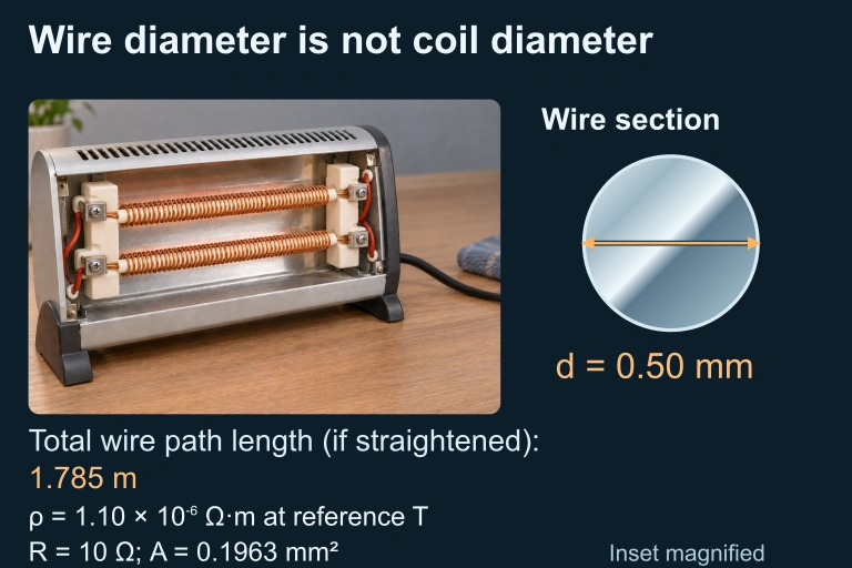 The magnified conductor section has diameter 0.50 mm. Its total path length, if straightened, is 1.785 m; this is not the heater housing width. At the stated reference temperature, resistivity 1.10×10⁻⁶ Ω·m and area 0.1963 mm² give 10 Ω.
SECTION 7
Strengths and Limitations of Ohm's Law
Ohm's law is one of the most widely used relationships in physics and electrical engineering, but it is important to understand its domain of validity. It is not a fundamental law of nature in the same way that Maxwell's equations or conservation of energy are; rather, it is an empirical observation that holds for a specific class of materials under specific conditions. The table below contrasts when Ohm's law works well with situations where it breaks down.
| Strengths / Valid Regime | Limitations / Breakdown |
|---|---|
| Excellent for metals at constant temperature—V and I are strictly proportional. | Fails for semiconductor devices (diodes, transistors) where V–I curves are exponential or piecewise. |
| Simple and powerful for quick circuit analysis: any two of V, I, R determines the third. | Does not hold for materials where resistance changes significantly with current (e.g., filament lamps as they heat up). |
| R = ρL/A accurately predicts resistance for uniform conductors of known geometry. | Does not account for AC impedance effects (capacitance, inductance), which require complex impedance analysis. |
| Combines seamlessly with Kirchhoff's laws and series/parallel rules for multi-resistor circuits. | Breaks down at very high electric fields, where materials can undergo dielectric breakdown or exhibit non-linear conduction. |
Comparison of where Ohm's law applies and where it does not.
KEY TAKEAWAY
SECTION 8
Connection to Advanced Topics
The ideas of resistance and resistivity covered in AP Physics 2 serve as the foundation for more advanced treatments in university-level electromagnetism and solid-state physics. Below is a comparison of the AP-level treatment with the deeper frameworks you may encounter in subsequent courses.
| AP Physics 2 Treatment | Advanced / University Treatment |
|---|---|
| Resistance R is constant for ohmic materials: V = IR. | The Drude model explains resistance microscopically: electrons drift under E-field, colliding with lattice ions. Drift velocity = eEτ/m, where τ is the mean free time. |
| R = ρL/A with ρ as a given constant. | Resistivity is derived from carrier density n and mobility μ: ρ = 1/(nqμ). Band theory explains why n differs vastly between metals, semiconductors, and insulators. |
| Temperature dependence noted qualitatively: metals increase in ρ as T rises. | Quantitative models: Bloch-Grüneisen theory for phonon scattering in metals; Arrhenius behavior for semiconductors (ρ ∝ ). |
| DC circuits only; no frequency dependence. | AC impedance: Z = R + jX, incorporating capacitive and inductive reactance. Skin effect alters effective cross-sectional area at high frequencies. |
| Superconductivity mentioned as zero resistance below a critical temperature. | BCS theory: Cooper pairs of electrons form a condensate that moves without scattering. Meissner effect expels magnetic fields. |
AP-level concepts and their advanced extensions.
While the AP Physics 2 curriculum does not require knowledge of the Drude model or band theory, understanding that resistance arises from microscopic scattering events gives you valuable physical intuition. When you encounter questions about why resistance changes with temperature or why different materials have vastly different resistivities, you can reason from the idea that anything that changes the frequency or severity of electron-lattice collisions will alter the resistance.
SECTION 9
Practice Problems
Question 1: CONCEPTUAL
- A. = 2
- B. = / 2
- C. = / 4
- D. = 4
Show answer (C)
Question 2: BASIC CALCULATION
- A. 2.7 Ω
- B. 30 Ω
- C. 3.0 Ω
- D. 0.033 Ω
Show answer (B)
Question 3: INTERMEDIATE
- A. R ≈ 0.27 Ω, I ≈ 44 A
- B. R ≈ 2.7 Ω, I ≈ 4.4 A
- C. R ≈ 0.027 Ω, I ≈ 440 A
- D. R ≈ 0.27 Ω, I ≈ 4.4 A
Show answer (A)
Question 4: APPLIED
5 ptsShow answer
Question 5: CRITICAL THINKING
4 ptsShow answer
SUMMARY
Summary
Summary
Ohm's law (V = IR) establishes that the voltage across an ohmic conductor is directly proportional to the current through it, with resistance R (measured in ohms, Ω) as the constant of proportionality. The resistance of a uniform conductor is governed by the equation R = ρL/A, where resistivity ρ is an intrinsic material property (Ω·m), L is the length along the direction of current flow, and A is the cross-sectional area perpendicular to the current. Resistance increases with length and resistivity but decreases with larger cross-sectional area.
For the AP Physics 2 exam, remember that non-ohmic devices (diodes, filament bulbs) produce curved V–I graphs, while ideal resistors produce straight lines through the origin. Power dissipation in a resistor can be calculated using P = IV = I²R = V²/R. Finally, temperature affects resistivity: metals become more resistive at higher temperatures due to increased lattice vibrations, while conductivity in semiconductors behaves more complexly. Mastering these relationships—along with the ability to interpret V–I graphs—provides the essential foundation for all circuit analysis on the exam.