
SECTION 1
Historical Context & Motivation
The bending of light as it passes from one transparent material into another is one of the oldest observed optical phenomena. Ancient civilizations noticed that objects partially submerged in water appeared displaced or distorted, yet a rigorous explanation eluded natural philosophers for centuries. The quest to quantify refraction — the change in direction of a wave as it crosses a boundary between two media with different optical properties — drove breakthroughs in both experimental measurement and mathematical reasoning that underpin modern optics, lens design, and fiber-optic communication.
~100 CE • Ptolemy's Measurements
1621 • Snell's Discovery
1637 • Descartes' Publication
1662 • Fermat's Principle of Least Time
1850 • Foucault Measures Light Speed in Water
The central question that refraction addresses is deceptively simple: why does light change direction when it enters a new medium, and by how much? Answering this question requires connecting the macroscopic behavior of light rays to the microscopic fact that light travels at different speeds in different materials. This connection — encoded in the index of refraction — is the thread that ties together every topic in this lesson.
SECTION 2
Core Principles & Definitions
Refraction rests on a small set of interconnected ideas. Before diving into the mathematics, it is essential to build precise definitions and physical intuition for each concept. The following foundational principles form the backbone of every refraction problem you will encounter on the AP Physics 2 exam.
Index of Refraction (n)
Snell's Law
The Normal Line
Total Internal Reflection
Wavelength Dependence (Dispersion)
KEY TAKEAWAY
SECTION 3
Visual Explanation — Refraction at an Interface
The diagram above captures the essential geometry of refraction at a flat boundary. Notice three key features. First, all angles are measured from the normal — this is a universal convention in optics and one of the most common sources of error on the AP exam if forgotten. Second, when light enters a medium with a higher index of refraction (from air into glass, for instance), the refracted ray bends toward the normal, making θ₂ < θ₁. Conversely, light exiting into a less optically dense medium bends away from the normal. Third, at every refraction event a partial reflection also occurs; the reflected ray obeys the law of reflection (angle of incidence equals angle of reflection) independently of the refraction process.
SECTION 4
Mathematical Framework
The mathematics of refraction centers on two relationships: the definition of the index of refraction and Snell's law. From these, the critical-angle condition and the wavelength shift inside a medium follow as direct consequences.
INDEX OF REFRACTION
n = index of refraction (dimensionless, always ≥ 1 for ordinary matter); c = speed of light in vacuum (3.00 × 10⁸ m/s); v = phase speed of light in the medium.
SNELL'S LAW
n₁ and n₂ are the indices of the first and second media; θ₁ is the angle of incidence; θ₂ is the angle of refraction. Both angles are measured from the normal to the interface.
CRITICAL ANGLE
θ_c is the critical angle in the denser medium. For angles of incidence greater than θ_c, total internal reflection occurs and no light is transmitted into the second medium.
WAVELENGTH IN A MEDIUM
λ₀ is the wavelength in vacuum; λ_n is the wavelength inside a medium with index n. The frequency f remains unchanged when light enters a new medium; only the wavelength and speed change.
A common conceptual pitfall is to assume that refraction changes the frequency of light. It does not. The frequency is set by the source and is preserved across every boundary. What changes is the wavelength and the speed, both decreasing by the same factor n. This can be understood from the wave relation v = fλ: if v decreases by a factor of n and f is constant, then λ must also decrease by the same factor.
Deriving Snell's Law from Fermat's Principle
SECTION 5
Total Internal Reflection & Critical Angle
When light travels from a medium with a higher index of refraction into one with a lower index — for example from water into air — the refracted ray bends away from the normal. As the angle of incidence increases, the refracted angle increases even faster, approaching 90°. The specific angle of incidence at which the refracted ray would lie exactly along the interface (θ₂ = 90°) is called the critical angle θ_c. For any angle of incidence exceeding θ_c, Snell's law yields sin θ₂ > 1, which has no real solution — physically, no refracted ray can exist and all incident energy is reflected. This phenomenon is total internal reflection (TIR).
| Interface | n₁ (denser) | n₂ (less dense) | Critical Angle θ_c |
|---|---|---|---|
| Water → Air | 1.33 | 1.00 | 48.8° |
| Glass → Air | 1.50 | 1.00 | 41.8° |
| Diamond → Air | 2.42 | 1.00 | 24.4° |
| Glass → Water | 1.50 | 1.33 | 62.5° |
Critical angles for common material pairs
Diamond's extremely high index of refraction (n = 2.42) produces a very small critical angle of only 24.4°, meaning that light entering a diamond is easily trapped by total internal reflection at many internal facets. This is precisely why diamonds exhibit such brilliant sparkle — skilled gem cutting maximizes the number of TIR events before light eventually exits through the top of the stone.
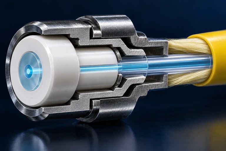 A fiber guides light by total internal reflection at its core–cladding boundary. The critical angle is measured from the sidewall normal; the entrance acceptance angle is measured from the fiber axis.
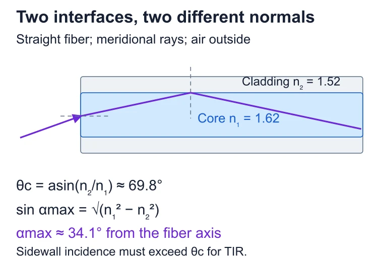 A fiber guides light by total internal reflection at its core–cladding boundary. The critical angle is measured from the sidewall normal; the entrance acceptance angle is measured from the fiber axis.
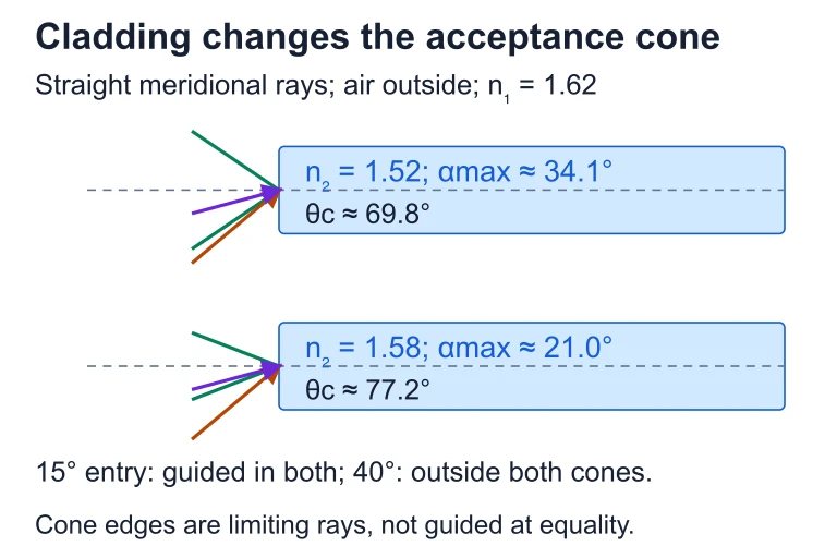 With core index 1.62 and light entering from air, raising the cladding index from 1.52 to 1.58 narrows the limiting acceptance half-angle from about 34.1° to 21.0°.
SECTION 6
Worked Example — Snell's Law and Critical Angle
A beam of monochromatic light traveling in water (n = 1.33) strikes a flat glass surface (n = 1.52) at an angle of incidence of 35.0°. Determine (a) the angle of refraction inside the glass and (b) the critical angle for light attempting to travel from the glass back into the water.
Snell's Law: Water → Glass
- 1
Step 1 — Identify Given Values
n₁ = 1.33 (water), n₂ = 1.52 (glass), θ₁ = 35.0°. We seek θ₂, the angle of refraction in the glass. - 2
Step 2 — Apply Snell's Law
n₁ sin θ₁ = n₂ sin θ₂ → sin θ₂ = (n₁ / n₂) sin θ₁ = (1.33 / 1.52) × sin 35.0°. - 3
Step 3 — Evaluate Numerically
sin 35.0° = 0.5736. Therefore sin θ₂ = (0.8750)(0.5736) = 0.5019. - 4
Step 4 — Solve for θ₂
θ₂ = sin⁻¹(0.5019).θ₂ ≈ 30.1° - 5
Step 5 — Reasonableness Check
Light is entering a denser medium (n₂ > n₁), so the refracted ray should bend toward the normal, meaning θ₂ < θ₁. Indeed, 30.1° < 35.0°. ✓ - 6
Step 6 — Critical Angle (Glass → Water)
For total internal reflection at the glass–water interface, sin θ_c = n₂ / n₁ = 1.33 / 1.52 = 0.8750. Therefore θ_c = sin⁻¹(0.8750).θ_c ≈ 61.0°
AP Exam Tip
SECTION 7
Applications, Strengths & Limitations
Refraction is not merely a textbook phenomenon; it underpins a vast range of technologies and natural phenomena. However, the simplified ray-optics treatment presented here carries certain limitations, particularly when wave effects like diffraction become significant. The table below contrasts the strengths and limitations of the geometric-optics model of refraction.
| Aspect | Strengths | Limitations |
|---|---|---|
| Lens & prism design | Snell's law accurately predicts image formation in converging and diverging lenses, enabling design of cameras, eyeglasses, and microscopes. | Chromatic aberration (dispersion) requires more complex multi-lens systems that the simple single-interface treatment does not address. |
| Fiber optics | Total internal reflection is the core mechanism for light propagation in optical fibers, carrying internet data across continents. | Signal attenuation, modal dispersion, and evanescent-wave leakage require wave-optics and materials-science models beyond ray tracing. |
| Natural phenomena | Explains mirages, the apparent bending of sticks in water, and the basic mechanism behind rainbows. | Atmospheric refraction in continuous-gradient media requires integration over varying n(h), not a single-interface application. |
| Scale of applicability | Works extremely well when wavelength ≪ size of optical elements (typical for visible light with centimeter-scale lenses). | Fails when structures approach the wavelength of light — diffraction gratings, thin films, and nano-optics require wave-optics treatment. |
Strengths and limitations of the geometric-optics treatment of refraction
KEY TAKEAWAY
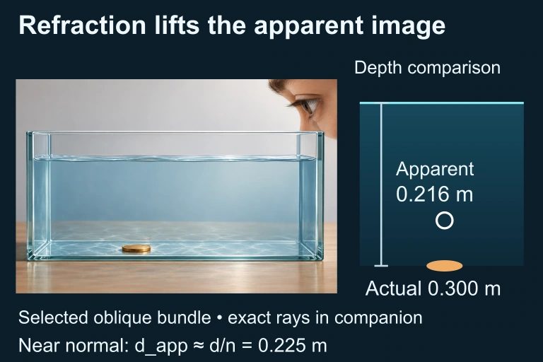 Exact Snell rays from a coin 0.300 m below water cross the surface at x=0.05 and 0.06 m. Backward extensions meet at depth 0.216 m for this local oblique bundle. The near-normal approximation gives 0.225 m and is a different viewing limit.
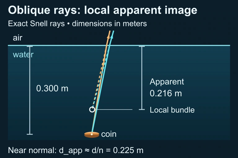 Exact Snell rays and local backward intersection
SECTION 8
Connections to Wave Optics & Modern Physics
Refraction as treated in geometric optics is a limiting case of the broader wave-optics description. Understanding how these two frameworks relate provides crucial context for topics you may encounter in later physics courses or in the wave-optics portion of AP Physics 2 itself.
| Feature | Geometric Optics (This Lesson) | Wave Optics / Modern Extensions |
|---|---|---|
| Light model | Light treated as rays that obey Snell's law at sharp boundaries. | Light treated as electromagnetic waves governed by Maxwell's equations; Fresnel equations give exact reflection/transmission amplitudes. |
| Wavelength effects | Dispersion noted but not deeply modeled; each wavelength simply has a different n. | Dispersion curves n(λ) are derived from oscillator models of electron response in materials; anomalous dispersion near absorption resonances. |
| Thin films | Not addressed; ray model cannot explain constructive/destructive interference in thin coatings. | Thin-film interference uses superposition of reflected wavefronts from top and bottom surfaces. |
| Photon picture | Not used; refraction is described entirely classically. | Quantum electrodynamics (QED) explains refraction as photon scattering by atomic electrons that re-radiate coherently, producing an effective slowing. |
Geometric optics vs. wave optics and modern physics
On the AP Physics 2 exam, you are expected to know that refraction arises from a change in wave speed at a boundary and that the wave model explains this via wavefront bending (Huygens' construction). The transition to thin-film interference and diffraction in later units builds directly on the refraction concepts established here — particularly the idea that wavelength changes inside a medium while frequency does not. Mastering refraction therefore creates a strong foundation for the wave-optics topics that follow.
SECTION 9
Practice Problems
Question 1: CONCEPTUAL
- A. Frequency only
- B. Wavelength and speed, but not frequency
- C. Speed only
- D. Frequency, wavelength, and speed all change
Show answer (B)
Question 2: BASIC CALCULATION
- A. 28.2°
- B. 35.2°
- C. 41.7°
- D. 50.0°
Show answer (B)
Question 3: INTERMEDIATE
- A. 1.10
- B. 1.22
- C. 1.38
- D. 1.84
Show answer (B)
Question 4: APPLIED
5 ptsShow answer
Question 5: CRITICAL THINKING
4 ptsShow answer
SUMMARY
Refraction — Key Concepts at a Glance
Summary
Refraction is the bending of light at the boundary between two media that arises because light travels at different speeds in different materials. The index of refraction n = c/v quantifies how much a medium slows light relative to vacuum. Snell's law (n₁ sin θ₁ = n₂ sin θ₂) relates the angles of incidence and refraction measured from the normal. When light enters a denser medium (higher n) it bends toward the normal; when it enters a less dense medium it bends away.
When light travels from a higher-n medium to a lower-n medium, there exists a critical angle θ_c = sin⁻¹(n₂/n₁) beyond which total internal reflection occurs. Frequency is conserved across boundaries, while wavelength and speed both change by the factor 1/n. These principles underpin lenses, prisms, fiber-optic communication, and dispersion — the wavelength dependence of n that splits white light into its component colors.