
SECTION 1
Historical Context & Motivation
The study of reflection is one of the oldest branches of physics, predating even the formal concept of a "law of nature." Ancient civilizations observed that polished metal surfaces and still water produced images, and Greek philosophers sought geometric explanations for this behavior. The law of reflection — deceptively simple in its statement — became one of the first quantitative principles in optics and remains a cornerstone of geometric optics today.
~300 BCE • Euclid's Optica
~60 CE • Hero of Alexandria
1621 • Snell's Law & Renewed Interest
1662 • Fermat's Principle
The central question reflection addresses is straightforward: when electromagnetic radiation encounters a boundary between two media, what determines the direction of the wave that bounces back? Understanding this question leads directly to the design of mirrors, telescopes, fiber-optic systems, and everyday phenomena such as seeing your own image in a window.
SECTION 2
Core Principles & Definitions
Reflection occurs whenever a wave encounters a boundary and part of its energy is redirected back into the original medium. In geometric optics we model light as rays and track their directions before and after they strike a surface. All analysis rests on a few precisely defined geometric quantities.
Normal Line
Angle of Incidence (θᵢ)
Angle of Reflection (θᵣ)
Plane of Incidence
SECTION 3
Visual Explanation — The Law of Reflection
In the diagram above, notice that both angles are measured from the normal — a frequent source of error on the AP exam. If a problem states that light hits a surface at 25° from the surface, the angle of incidence is actually 90° − 25° = 65° from the normal. The coplanarity condition means the three-dimensional problem reduces to two dimensions within the plane of incidence, simplifying ray tracing enormously.
SECTION 4
Mathematical Framework
The Law of Reflection
LAW OF REFLECTION
θi = angle of incidence (measured from the normal), θr = angle of reflection (measured from the normal). Both rays and the normal are coplanar.
This law holds for every type of reflection — specular, diffuse, or anything in between — because it applies at the local surface normal at each point. For a flat (plane) mirror, the normal is the same everywhere, so a parallel bundle of rays reflects as a parallel bundle, preserving the image. For a curved surface, each infinitesimal patch has its own normal, and the law still applies point by point.
Deriving Image Location for a Plane Mirror
PLANE MIRROR IMAGE DISTANCE
do = object distance (positive, in front of mirror), di = image distance (negative because the image is behind the mirror). The image is virtual, upright, and the same size as the object.
Curved Mirror Equation
MIRROR EQUATION
f = focal length (positive for concave, negative for convex), do = object distance, di = image distance. The focal length relates to the radius of curvature by f = R/2.
MAGNIFICATION
M = lateral magnification, hi = image height, ho = object height. If M > 0 the image is upright; if M < 0 it is inverted. |M| > 1 means the image is enlarged.
SECTION 5
Types of Reflection
The law of reflection (θᵢ = θᵣ) applies at every point on every surface, yet the macroscopic result depends on the surface's geometry. Two limiting cases — specular reflection and diffuse reflection — bracket a continuum that determines whether a surface acts as a mirror or simply scatters light.
| Property | Specular Reflection | Diffuse Reflection |
|---|---|---|
| Surface texture | Smooth (irregularities ≪ λ) | Rough (irregularities ≥ λ) |
| Reflected rays | Parallel bundle preserved | Scattered in many directions |
| Image formed? | Yes — clear, defined image | No — object is illuminated but not imaged |
| Example | Glass mirror, still lake | Paper, matte paint, unpolished wood |
| Law of reflection | θᵢ = θᵣ at every point (same normal) | θᵢ = θᵣ at every point (varying normals) |
Specular vs. diffuse reflection comparison
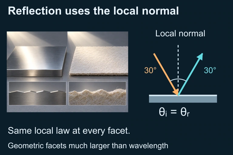 A large local facet illustrates equal incidence and reflection angles. The companion changes facet slopes while preserving the incoming direction, so reflected directions differ without violating the same local law. This idealized ray model requires facets much larger than the wavelength.
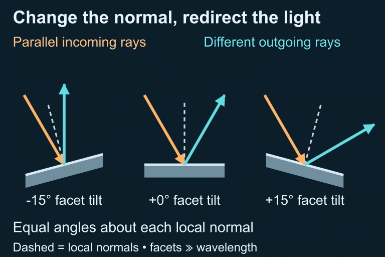 Computed reflection at three local facet tilts
SECTION 6
Worked Example — Concave Mirror Imaging
A concave mirror has a radius of curvature R = 40.0 cm. An object 3.0 cm tall is placed 30.0 cm in front of the mirror. Find the image distance, the magnification, and describe the image (real/virtual, upright/inverted, enlarged/reduced).
Worked example
- 1
Step 1 — Find the Focal Length
The focal length of a spherical mirror is half the radius of curvature: f = R/2 = 40.0 cm / 2 = 20.0 cm. Because the mirror is concave, f is positive in the standard sign convention.f = +20.0 cm - 2
Step 2 — Apply the Mirror Equation
Using 1/f = 1/dₒ + 1/dᵢ, we substitute: 1/20.0 = 1/30.0 + 1/dᵢ. Solving for 1/dᵢ: 1/dᵢ = 1/20.0 − 1/30.0 = (3 − 2)/60 = 1/60. Therefore dᵢ = 60.0 cm.dᵢ = +60.0 cm - 3
Step 3 — Calculate Magnification
M = −dᵢ/dₒ = −60.0/30.0 = −2.0. The image height is hᵢ = M × hₒ = (−2.0)(3.0 cm) = −6.0 cm.M = −2.0 ; hᵢ = −6.0 cm - 4
Step 4 — Characterize the Image
Since dᵢ is positive, the image forms in front of the mirror and is real. The negative magnification tells us the image is inverted. Because |M| = 2.0 > 1, the image is enlarged (twice the object height).Real, inverted, enlarged image at 60.0 cm from the mirror
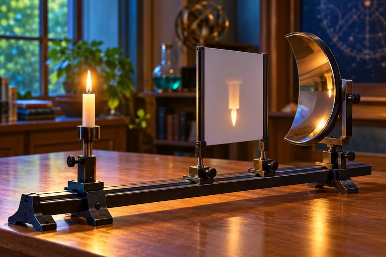 A concave mirror forms a real image where reflected rays converge. When the object is inside the focal length, the reflected rays diverge and their backward extensions locate an upright virtual image.
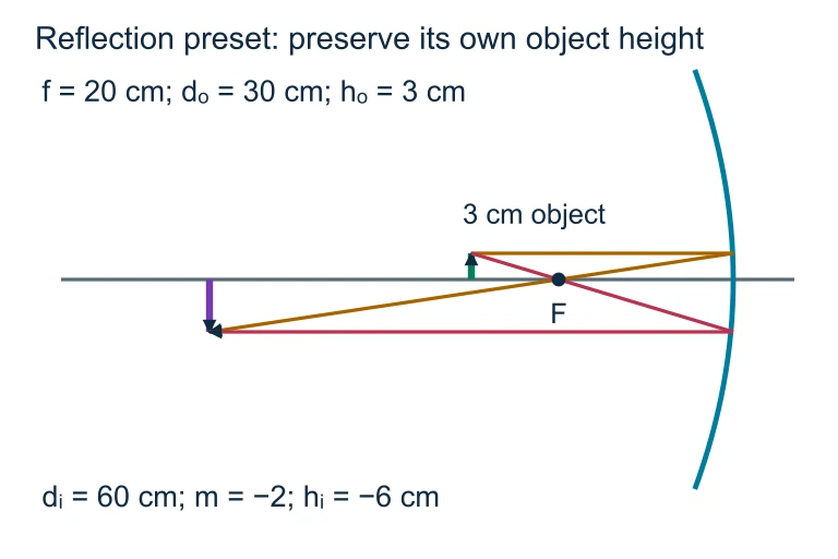 With f = 20 cm and object distance 30 cm, the image distance is 60 cm and magnification is −2. A 3 cm object therefore forms an inverted 6 cm image.
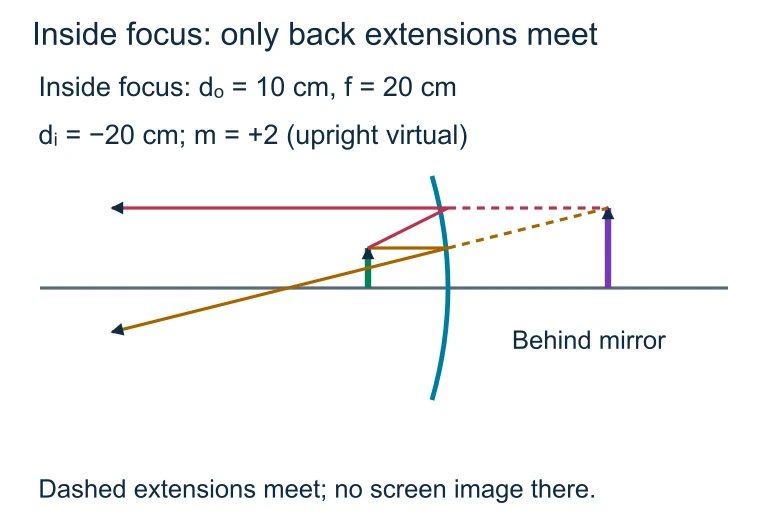 An object 10 cm in front of a concave mirror with f = 20 cm has image distance −20 cm and magnification +2. Only backward extensions meet behind the mirror.
SECTION 7
Comparing Mirror Geometries
Mirrors come in three basic geometries — plane, concave, and convex — each producing distinct image characteristics. Selecting the right mirror for an application depends on whether you need a real, projectable image (concave) or a wide field of view with a virtual image (convex), or simply a faithful, same-size image (plane). The table below summarizes their properties as they are typically tested on the AP Physics 2 exam.
| Property | Plane Mirror | Concave Mirror | Convex Mirror |
|---|---|---|---|
| Focal length | f → ∞ | f > 0 (f = R/2) | f < 0 (f = −R/2) |
| Image type | Always virtual | Real or virtual (depends on dₒ) | Always virtual |
| Image orientation | Upright | Inverted (real) or upright (virtual) | Always upright |
| Magnification | |M| = 1 always | |M| can be > 1, = 1, or < 1 | |M| < 1 always |
| Common use | Bathroom mirrors | Telescopes, headlights, solar concentrators | Side-view car mirrors, security mirrors |
Comparison of plane, concave, and convex mirrors
SECTION 8
Connection to Wave Optics & Advanced Theory
Geometric optics treats light as rays, an approximation valid when the wavelength λ is much smaller than the dimensions of optical components. When surfaces or apertures approach the wavelength scale, wave phenomena — interference and diffraction — become significant, and the ray model breaks down. Reflection in the wave picture is governed by Maxwell's equations and the boundary conditions at an interface, which yield the Fresnel equations for reflectance and transmittance as functions of angle and polarization.
| Aspect | Geometric Optics (This Course) | Wave / Physical Optics |
|---|---|---|
| Model of light | Rays (straight lines) | Electromagnetic waves |
| Reflection law | θᵢ = θᵣ (direction only) | Fresnel equations (direction + amplitude + phase) |
| Accounts for polarization? | No | Yes — s- and p-polarization reflect differently |
| Partial reflection intensity | Not predicted | Quantified by reflectance R(θ) |
| Valid when | λ ≪ size of objects | Always (more general) |
Geometric vs. wave treatment of reflection
For AP Physics 2, you are expected to use the geometric (ray) model but should be aware that it is an approximation. The wave nature of light becomes important in the interference and diffraction units later in the course, and the concept of total internal reflection — where refracted rays vanish and all light is reflected — bridges both models.
SECTION 9
Practice Problems
Question 1: CONCEPTUAL
- A. 35°
- B. 55°
- C. 70°
- D. 110°
Show answer (A)
Question 2: BASIC CALCULATION
- A. 16.7 cm
- B. 50.0 cm
- C. −16.7 cm
- D. 25.0 cm
Show answer (A)
Question 3: INTERMEDIATE
- A. 30 cm
- B. 45 cm
- C. 15 cm
- D. 10 cm
Show answer (A)
Question 4: APPLIED
Show answer
Question 5: CRITICAL THINKING