
SECTION 1
Historical Context & Motivation
The connection between electricity and magnetism was not always obvious—these phenomena were studied as completely separate branches of natural philosophy for centuries. Ancient civilizations were familiar with lodestones, naturally magnetized pieces of magnetite that could attract iron, while the Greeks recognized that rubbed amber could attract lightweight objects. It was not until the early nineteenth century that a pivotal lecture demonstration revealed the deep link between electric current and magnetic phenomena, launching the field of electromagnetism. The decades that followed produced a cascade of discoveries that culminated in a unified mathematical description of electric and magnetic fields, fundamentally changing our understanding of nature and enabling the technologies that define modern life.
1820 • Ørsted's Discovery
1820 • Biot-Savart Law
1820–1825 • Ampère's Force Law
1831 • Faraday's Induction
1865 • Maxwell's Equations
These discoveries raised a central question that this lesson addresses: exactly how does a current-carrying wire interact with a magnetic field, and how can we predict both the force on the wire and the magnetic field the wire itself creates? Understanding these interactions is essential for analyzing motors, solenoids, and the transmission of electrical power.
SECTION 2
Core Principles & Definitions
Before diving into calculations, it is important to establish the foundational ideas that govern the behavior of current-carrying wires in magnetic fields. The physics rests on two complementary perspectives: a wire carrying current produces its own magnetic field in the surrounding space, and simultaneously, if that wire is placed in an external magnetic field, the field exerts a force on the wire. Both effects arise from the same underlying principle—moving charges are the source of magnetic fields and the objects upon which magnetic fields act.
Magnetic Field from a Wire
Force on a Wire in an External Field
Right-Hand Rules
Force Between Parallel Wires
KEY TAKEAWAY
SECTION 3
Visual Explanation — Field Around a Wire
The diagram above illustrates the fundamental geometry of the magnetic field surrounding a long, straight conductor. Notice that the field lines form closed loops, a defining characteristic of magnetic fields—unlike electric field lines, which begin and end on charges, magnetic field lines always form closed loops. The three dashed circles at increasing radii emphasize that B is inversely proportional to the distance from the wire: doubling the distance halves the field strength. This 1/r dependence (rather than the 1/r² seen in point-charge electric fields) reflects the fact that the wire is an extended, one-dimensional source. The right-hand rule box in the upper-left corner summarizes the procedure: align your right thumb with the direction of conventional current, and your curled fingers indicate the circulation of the B field.
SECTION 4
Mathematical Framework
Two key equations govern the physics of current-carrying wires in magnetic fields. The first describes the magnetic field produced by a long, straight wire, and the second gives the force experienced by a current-carrying wire when placed in an external magnetic field. Both are central to the AP Physics 2 exam and appear in the equation sheet provided during the test.
MAGNETIC FIELD OF A LONG STRAIGHT WIRE
B = magnetic field magnitude (T), μ₀ = permeability of free space = 4π × 10−7 T·m/A, I = current (A), r = perpendicular distance from wire (m). The field direction is tangent to the circular field line at any point, found via the right-hand rule.
FORCE ON A CURRENT-CARRYING WIRE IN AN EXTERNAL FIELD
F = magnitude of force on the wire (N), I = current (A), L = length of wire in the field (m), B = external magnetic field magnitude (T), θ = angle between the direction of I and the direction of B. Maximum force when θ = 90°; zero force when θ = 0° (wire parallel to field).
FORCE PER UNIT LENGTH BETWEEN TWO PARALLEL WIRES
F/L = force per unit length (N/m), I₁ and I₂ = currents in wire 1 and wire 2 (A), d = distance between the wires (m). Currents in the same direction attract; currents in opposite directions repel.
The force between parallel wires can be derived by combining the first two equations. Wire 1 creates a field B₁ = μ₀I₁/(2πd) at the location of wire 2. The force on a length L of wire 2 in that field is F = I₂LB₁ = I₂L × μ₀I₁/(2πd), giving the result shown above. This derivation is a common AP Physics 2 free-response task and illustrates how two fundamental relationships combine to explain the interaction between conductors.
Direction of the Force
SECTION 5
Parallel Wires & Field Superposition
When two long, straight wires are placed parallel to each other and each carries a current, the situation combines both key ideas from this lesson: each wire generates a magnetic field, and each wire sits inside the field created by the other. The result is a mutual force between the wires whose direction depends on whether the currents are parallel (same direction) or antiparallel (opposite directions). This interaction was historically so fundamental that it was used to define the SI unit of current, the ampere, before the 2019 redefinition.
The diagram makes a critical point that is frequently tested: the direction of the force depends on the relative orientation of the two currents, not their absolute direction. To see why parallel currents attract, consider the field produced by wire 1 at the location of wire 2. Using the right-hand rule, if I₁ points upward, the field at wire 2's position points into the page (for wire 2 to the right of wire 1). Then the force on wire 2 (carrying current upward through a field into the page) is directed to the left—toward wire 1. A symmetric argument shows wire 1 is pulled toward wire 2. When the currents are antiparallel, the field direction reverses and the force pushes the wires apart.
AP Exam Tip
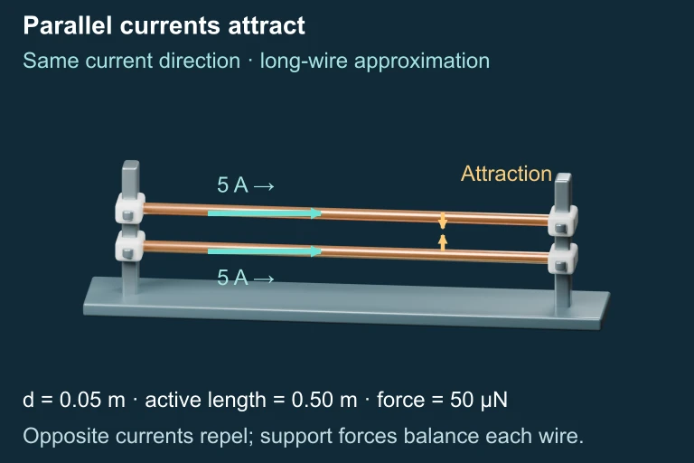 Equal parallel currents attract; reversing one current produces repulsion. The equal and opposite mutual forces are balanced by supports.
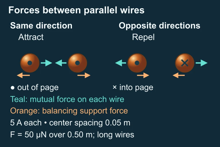 Cross sections compare mutual forces and support forces.
SECTION 6
Worked Example
Force on a Wire in a Uniform Magnetic Field
- 1
Step 1 — Read the Problem
A straight wire of length 0.50 m carries a current of 3.0 A and is placed in a uniform external magnetic field of magnitude 0.20 T. The wire is oriented at an angle of 30° relative to the field. Find the magnitude of the magnetic force on the wire. - 2
Step 2 — Identify the Relevant Equation
The force on a straight current-carrying wire in a uniform external field is given by F = ILB sin θ, where I is the current, L is the length of wire in the field, B is the field magnitude, and θ is the angle between the current direction and B. - 3
Step 3 — Substitute Known Values
F = (3.0 A)(0.50 m)(0.20 T) sin 30°. We know that sin 30° = 0.50, so this becomes F = (3.0)(0.50)(0.20)(0.50). - 4
Step 4 — Calculate
F = 3.0 × 0.50 × 0.20 × 0.50 = 0.15 N.F = 0.15 N - 5
Step 5 — Interpret and Check
The force is 0.15 N, which is less than the maximum possible force of ILB = 0.30 N that would occur if the wire were perpendicular to the field (θ = 90°). Since the wire is at only 30° to the field, the sin factor reduces the force by half, which is physically consistent. The direction of this force would be perpendicular to both the current and the field, determined by the right-hand rule.
Magnetic Field at a Point Near a Wire
- 1
Step 1 — Read the Problem
A long, straight wire carries a current of 10 A. Calculate the magnitude of the magnetic field at a point 0.04 m from the wire. - 2
Step 2 — Write the Equation
For a long, straight wire, B = μ₀I / (2πr), where μ₀ = 4π × 10⁻⁷ T·m/A. - 3
Step 3 — Substitute
B = (4π × 10⁻⁷ T·m/A)(10 A) / (2π × 0.04 m). Notice the π cancels: B = (4 × 10⁻⁷ × 10) / (2 × 0.04) = (4 × 10⁻⁶) / (0.08). - 4
Step 4 — Calculate
B = 5.0 × 10⁻⁵ T = 50 μT.B = 5.0 × 10⁻⁵ T (50 μT) - 5
Step 5 — Context Check
Earth's magnetic field is approximately 50 μT, so a 10 A current at 4 cm produces a field comparable to Earth's field. This is reasonable and illustrates why household wires (carrying several amperes) can deflect a compass at close range.
SECTION 7
Comparing Electric and Magnetic Forces on Charges
Students sometimes conflate electric and magnetic forces because both involve charges and fields. A clear comparison highlights important distinctions that appear frequently on the AP Physics 2 exam, particularly in qualitative and conceptual questions.
| Feature | Electric Force (F = qE) | Magnetic Force (F = qvB sin θ / F = ILB sin θ) |
|---|---|---|
| Acts on | Any charge (moving or stationary) | Only moving charges or current-carrying conductors |
| Direction relative to field | Parallel (or antiparallel) to E | Perpendicular to both v (or I) and B |
| Does work? | Yes — can change kinetic energy | No — force is always perpendicular to velocity, so it changes direction but not speed |
| Depends on velocity? | No | Yes — zero force if charge is stationary or moving parallel to B |
| Field lines | Begin on + charges, end on − charges (open lines) | Always form closed loops — no magnetic monopoles |
Comparison of electric and magnetic forces relevant to AP Physics 2
KEY TAKEAWAY
SECTION 8
Connection to Advanced Theory
The ideas in this lesson—forces on current-carrying wires and the fields they produce—form the foundation for several more advanced topics you will encounter later in the AP Physics 2 course and in college-level electromagnetism. Understanding how the concepts scale up provides motivation and context for deeper study.
| This Lesson (AP Physics 2) | Advanced Extension |
|---|---|
| B = μ₀I/(2πr) for a single long wire | Ampère's law (∮B·dl = μ₀I_enc) generalizes to any closed path and any current distribution, enabling calculation of fields for solenoids and toroids |
| F = ILB sin θ for a straight wire | Torque on a current loop (τ = NIAB sin θ) explains how motors rotate and how magnetic dipole moments arise |
| Force between two parallel wires | Electromagnetic induction (Faraday's law): changing currents in one wire induce EMFs in nearby conductors—basis of transformers |
| Right-hand rule for F = IL × B | Full vector cross-product formalism in calculus-based physics (F = qv × B), leading to Lorentz force and relativistic electrodynamics |
How this lesson's ideas connect to more advanced electromagnetism
Perhaps the most profound forward connection is that the force between two current-carrying wires can be understood from special relativity. In the rest frame of the moving charges in one wire, length contraction alters the apparent charge densities in the other wire, producing what appears to be a net electrostatic force. What we call the "magnetic force" is, at its deepest level, a relativistic correction to the electric force. While this derivation is well beyond the AP Physics 2 syllabus, it underscores a powerful idea: electricity and magnetism are two aspects of a single electromagnetic interaction, unified by Maxwell's equations and illuminated by Einstein's theory of relativity.
SECTION 9
Practice Problems
Question 1: CONCEPTUAL
- A. The force is directed to the right, parallel to the current.
- B. The force is directed downward, toward the wire.
- C. The force is directed upward, away from the wire.
- D. There is no magnetic force on the proton.
Show answer (D)
Question 2: BASIC CALCULATION
- A. 0.60 N
- B. 1.2 N
- C. 1.5 N
- D. 2.4 N
Show answer (B)
Question 3: INTERMEDIATE
- A. 1.6 × 10⁻⁵ N/m, repulsive
- B. 3.2 × 10⁻⁵ N/m, attractive
- C. 3.2 × 10⁻⁵ N/m, repulsive
- D. 6.4 × 10⁻⁵ N/m, attractive
Show answer (B)
Question 4: APPLIED
5 ptsShow answer
Question 5: CRITICAL THINKING
4 ptsShow answer
SUMMARY
Lesson Summary
Summary
This lesson explored two complementary aspects of magnetism and current-carrying wires. First, a long straight wire carrying current I produces a magnetic field B = μ₀I/(2πr) that forms concentric circular loops around the wire, with the direction given by the right-hand rule. The field decreases inversely with distance from the wire. Second, when a current-carrying wire of length L is placed in an external magnetic field, it experiences a force of magnitude F = ILB sin θ, which is maximum when the wire is perpendicular to the field and zero when parallel.
Combining these ideas explains the force between parallel wires: F/L = μ₀I₁I₂/(2πd), where parallel currents attract and antiparallel currents repel. The critical distinction between electric and magnetic forces is that magnetic forces act only on moving charges, are always perpendicular to the velocity, and do no work on individual charges. These principles underpin electric motors, generators, and electromagnetic induction—technologies that connect directly to the broader framework of Maxwell's equations.