AP Physics 2 • Electric Circuits

Kirchhoff's Loop Rule

Energy conservation applied to closed loops reveals how voltage rises and drops govern every circuit.

An atom with wave and electric energy symbols.
Inside this lesson 10 sections 5 questions 8 figures

SECTION 1

Historical Context & Motivation

In the mid-nineteenth century, the rapidly expanding telegraph industry demanded a rigorous way to predict voltages and currents in networks of wires and batteries. Ohm's law, published in 1827, elegantly related voltage, current, and resistance for a single element, but it could not handle branching wires or circuits with multiple batteries arranged in complex topologies. The physicist Gustav Kirchhoff recognized that two conservation laws — conservation of charge and conservation of energy — could be translated into algebraic rules that apply to any circuit, no matter how intricate. His two rules, published in 1845 when he was just twenty-one, remain cornerstones of electrical engineering and physics to this day.

1800 • Voltaic Pile Invented

Alessandro Volta creates the first true battery, providing a steady source of EMF and motivating the study of continuous current flow through conductors.

1827 • Ohm's Law Published

Georg Simon Ohm establishes the proportional relationship V = IR for a single resistive element, laying the groundwork for quantitative circuit analysis.

1845 • Kirchhoff's Circuit Laws

Gustav Kirchhoff formulates the junction rule (charge conservation) and the loop rule (energy conservation), enabling systematic solution of arbitrarily complex circuits.

1880s • Electrification Era

Edison and Westinghouse design large-scale power distribution networks. Kirchhoff's rules become essential engineering tools for analyzing series-parallel grids supplying thousands of loads.

Modern • SPICE and Digital Simulation

Computer-aided circuit simulators like SPICE solve Kirchhoff's equations for circuits with millions of components, confirming that his 1845 framework scales from classroom problems to microprocessor design.

The central question Kirchhoff's loop rule addresses is deceptively simple: if a charge travels around any closed path in a circuit and returns to its starting point, what is the net change in its electrical potential energy? Because energy is conserved, that net change must be zero — and the loop rule is the precise mathematical statement of that fact. Mastering this rule equips you to analyze multi-loop circuits that Ohm's law alone cannot solve.

SECTION 2

Core Principles & Definitions

Kirchhoff's loop rule — sometimes called the voltage law or KVL — is grounded in the principle that the electrostatic field is conservative. When a test charge completes a closed loop, the work done on it by the electric field sums to zero, which means the algebraic sum of all potential differences (voltage rises and drops) around any closed loop must equal zero. Before diving into the mathematics, it is essential to understand the foundational ideas that give the rule its power.

1

Conservative Electric Field

The electric field in electrostatics is conservative: the work done on a charge around any closed path is zero. This is the physical basis for the loop rule.
2

EMF as Energy Source

A battery or other electromotive force (EMF) device converts chemical or other energy into electrical potential energy, providing a voltage rise to charges passing through it.
3

Voltage Drop Across Resistors

As current flows through a resistor, electrical potential energy is converted to thermal energy. The voltage drop equals IR by Ohm's law, and the sign depends on the direction of traversal relative to current.
4

Sign Convention

Choose a traversal direction around the loop. Traversing a resistor in the direction of current yields −IR (a drop); traversing against current yields +IR. Moving from − to + through a battery yields +ε; from + to − yields −ε.
5

Loop Independence

The loop rule applies to every closed path in a circuit, including paths that share branches. For a circuit with N independent loops, the loop rule generates N independent equations.
✦

KEY TAKEAWAY

Think of the loop rule like a hiker walking a trail that returns to the starting elevation. No matter how many hills (batteries providing voltage rises) and valleys (resistors causing voltage drops) the hiker traverses, the net elevation change over the complete loop is exactly zero. In a circuit, electric potential plays the role of elevation: every joule of energy a battery gives to each coulomb of charge is dissipated by the resistors in the loop.

SECTION 3

Visual Explanation — A Single-Loop Circuit

ε+−R₁R₂R₃ILoopABCDEKirchhoff's Loop Rule — Single-Loop Circuitε − IR₁ − IR₂ − IR₃ = 0
A single-loop series circuit containing a battery of EMF ε and three resistors R₁, R₂, and R₃. The dashed loop arrow indicates the chosen traversal direction (clockwise). Starting at point A and summing voltage changes around the loop yields the equation shown at the bottom.

In the diagram above, consider a positive test charge starting at point A. As it moves clockwise, it first encounters resistor R₁, losing potential energy (voltage drop of −IR₁). Continuing through R₂ and R₃, it loses additional amounts −IR₂ and −IR₃. Finally, traversing the battery from its negative terminal to its positive terminal, the charge gains potential energy (+ε). Because the charge returns to point A at the same potential, the total sum must be zero. This is Kirchhoff's loop rule in action.

💡

Sign Convention Tip

When traversing a resistor in the direction of assumed current, record a voltage drop (−IR). When traversing against the assumed current, record a voltage rise (+IR). If your assumed current direction turns out to be wrong, the algebra will yield a negative value for the current — the physics self-corrects.

SECTION 4

Mathematical Framework

The loop rule translates the abstract principle of energy conservation into a concrete algebraic equation. For any closed loop, the signed sum of all EMFs and all resistive voltage drops equals zero. This statement can be written compactly using summation notation and then applied systematically to circuits of any complexity.

KIRCHHOFF'S LOOP RULE (KVL)

∑ΔV=0aroundanyclosedloop∑ ΔV = 0 around any closed loop

ΔV represents each voltage change (rise or drop) encountered as you traverse the loop. This includes EMF sources and resistive elements.

EXPANDED FORM — SERIES LOOP

ε1+ε2+…−IR1−IR2−…=0ε₁ + ε₂ + … − I R₁ − I R₂ − … = 0

εk = EMF of the k-th source (positive if traversed from − to +). I = current through the loop. Rk = resistance of the k-th resistor.

SOLVING FOR CURRENT (SINGLE LOOP)

I=(ε1+ε2+…)/(R1+R2+…)I = (ε₁ + ε₂ + …) / (R₁ + R₂ + …)

When all sources push current in the same direction, the total EMF divides by the total resistance — recovering the familiar result for series resistors.

For multi-loop circuits, you must write one loop equation for each independent loop and simultaneously solve the resulting system of equations. In conjunction with Kirchhoff's junction rule (∑Iin = ∑Iout at every node), the loop rule provides exactly enough independent equations to solve for all unknown currents and voltages. The general algorithm involves: (1) assign current variables and directions to each branch, (2) apply the junction rule at enough nodes, (3) apply the loop rule around enough independent loops, and (4) solve the resulting linear system.

ℹ

Exam Strategy

On the AP Physics 2 exam, if you obtain a negative value for a current, do not panic — it simply means the actual current flows opposite to your assumed direction. Always report the magnitude and state the correct direction.

SECTION 5

Detailed Breakdown — Sign Convention Rules

The most common source of errors in applying the loop rule is incorrect sign assignment. A systematic approach removes ambiguity: choose a traversal direction for each loop, then apply the following rules consistently for every element you cross. The diagram below illustrates all four cases you will encounter.

Sign Convention — All Four CasesCase 1: Resistor — With CurrentRITraversal →ΔV = −IRCase 2: Resistor — Against CurrentRITraversal →ΔV = +IRCase 3: Battery − to + (Rise)−+εTraversal →ΔV = +εCase 4: Battery + to − (Drop)+−εTraversal →ΔV = −ε
The four sign convention cases encountered when traversing a loop. The dashed cyan arrow represents the chosen traversal direction, and the yellow arrow represents current direction. Green results indicate voltage rises; red results indicate voltage drops.
ElementTraversal DirectionVoltage Change
ResistorSame as current direction−IR (drop)
ResistorOpposite to current direction+IR (rise)
Battery / EMFFrom − terminal to + terminal+ε (rise)
Battery / EMFFrom + terminal to − terminal−ε (drop)

Summary of sign conventions for the loop rule

SECTION 6

Worked Example — Two-Battery Loop

Consider a single-loop circuit containing two batteries and two resistors. Battery ε₁ = 12.0 V is in series with R₁ = 4.0 Ω, and battery ε₂ = 6.0 V opposes ε₁, in series with R₂ = 8.0 Ω. The batteries and resistors form a single closed loop. Determine the current in the loop and the voltage across each resistor.

Two-Battery Single-Loop Analysis

  1. 1

    Step 1 — Assign Current Direction

    Assume a clockwise current I through the loop. Because ε₁ > ε₂, we expect ε₁ to drive the current, so clockwise is a reasonable assumption. If we are wrong, the algebra will yield a negative I.
  2. 2

    Step 2 — Choose Traversal Direction & Starting Point

    Traverse the loop clockwise, starting just before the positive terminal of ε₁. This matches our assumed current direction, simplifying sign tracking.
  3. 3

    Step 3 — Write the Loop Equation

    Starting at the negative terminal of ε₁ and moving clockwise: traverse ε₁ from − to + → +ε₁; traverse R₁ in the direction of I → −IR₁; traverse ε₂ from + to − (opposing) → −ε₂; traverse R₂ in the direction of I → −IR₂. Setting the sum to zero: ε₁ − IR₁ − ε₂ − IR₂ = 0.
  4. 4

    Step 4 — Solve for Current

    Rearranging: I(R₁ + R₂) = ε₁ − ε₂. Substituting values: I = (12.0 V − 6.0 V) / (4.0 Ω + 8.0 Ω) = 6.0 V / 12.0 Ω.
    I = 0.50 A (clockwise)
  5. 5

    Step 5 — Find Voltage Drops

    VR₁ = IR₁ = (0.50 A)(4.0 Ω) = 2.0 V. VR₂ = IR₂ = (0.50 A)(8.0 Ω) = 4.0 V.
    VRV_R₁ = 2.0 V, VRV_R₂ = 4.0 V
  6. 6

    Step 6 — Verify with Loop Rule

    Check: +12.0 − 2.0 − 6.0 − 4.0 = 0.0 V ✓. The algebraic sum of all voltage changes around the loop is indeed zero, confirming our answer and sign assignments.
    ∑ΔV = 0 ✓

Clockwise loop 0→12→10→4→0 V and+12−2−6−4=0.A 12 V source supplies a series loop containing two resistors and an opposing 6 V source; the latter absorbs power.
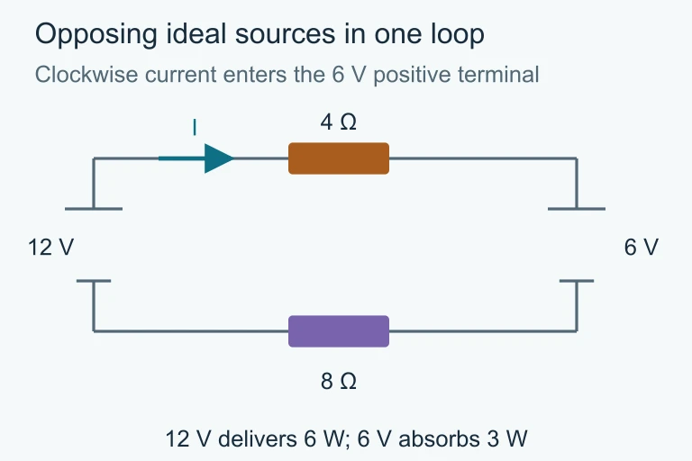
Opposing 12 and 6 V sources with 4 and 8 Ω: I 0.5 A;12 V source delivers 6 W,6 V source absorbs 3 W, resistors 3 W.Ideal circuit with polarities and component values.

SECTION 7

Strengths, Limitations & Comparisons

Kirchhoff's loop rule is remarkably versatile, but understanding its domain of validity helps you know when to apply it confidently and when modifications or alternative approaches may be needed. The following comparison highlights its strengths alongside its limitations in the context of AP Physics 2.

AspectStrengthsLimitations
GeneralityApplies to any circuit topology — series, parallel, or complex multi-loop networks with multiple EMF sources.Assumes a lumped-element model; does not account for distributed effects in transmission lines or antennas.
SimplicityRequires only algebra — no calculus — making it accessible and ideal for the AP Physics 2 curriculum.For circuits with many loops, the resulting system of linear equations can become tedious to solve by hand.
Physical BasisDirectly tied to energy conservation, providing deep conceptual grounding for every equation written.Strictly valid only for conservative electric fields; in circuits with time-varying magnetic flux, Faraday's law modifies the loop rule.
Error DetectionNegative current values automatically indicate an incorrect direction assumption — the method self-corrects.Sign errors in setting up the equation are common and can propagate, so careful bookkeeping is essential.

Strengths and limitations of Kirchhoff's loop rule

✦

KEY TAKEAWAY

In engineering practice, Kirchhoff's loop rule remains the backbone of circuit simulation software. SPICE and similar programs construct and solve loop (or node) equations for circuits with millions of components — the same fundamental idea you apply by hand on the AP exam, scaled up by computer algebra. Mastering the sign conventions and systematic equation-writing now builds a transferable skill for any field involving electrical systems.

SECTION 8

Connection to Advanced Theory

While Kirchhoff's loop rule is introduced in the context of DC circuits with steady currents, it connects to deeper ideas in electromagnetism. Understanding these connections will strengthen your conceptual framework and prepare you for topics encountered in more advanced coursework.

FeatureKirchhoff's Loop Rule (DC)Faraday's Law Extension (AC / Changing Flux)
Governing principle∑ΔV = 0 around any closed loop∑ΔV = −dΦ_B/dt (EMF induced by changing magnetic flux)
Electric field typeConservative (curl E = 0)Non-conservative component from time-varying B field
Applicable circuitsDC circuits with batteries and resistorsAC circuits, circuits with inductors and changing magnetic environments
AP Physics 2 scopeFully covered; required for multi-loop DC analysisConceptual awareness expected; quantitative treatment in AP Physics C

Kirchhoff's loop rule in the context of broader electromagnetic theory

In AP Physics 2, you should also recognize that the loop rule naturally extends to circuits containing capacitors. When a capacitor with charge Q and capacitance C appears in a loop, its voltage contribution is Q/C (with appropriate sign). This is critical for analyzing RC charging and discharging circuits qualitatively on the exam. Furthermore, the loop rule can be combined with Kirchhoff's junction rule (conservation of charge) to solve circuits that cannot be reduced by simple series-parallel combinations — a skill tested in multi-loop free-response questions.

SECTION 9

Practice Problems

Question 1: CONCEPTUAL

Kirchhoff's loop rule is a direct consequence of which fundamental conservation law?
  • A. Conservation of charge
  • B. Conservation of momentum
  • C. Conservation of energy
  • D. Conservation of angular momentum
Show answer (C)
Correct: C — Conservation of energy. Kirchhoff's loop rule states that the algebraic sum of all potential differences around any closed loop is zero (∑ΔV = 0). This is equivalent to saying that a charge traversing a complete loop returns to the same electric potential, meaning its net change in electrical potential energy is zero — a direct expression of energy conservation. Choice A is incorrect because conservation of charge is the basis of Kirchhoff's junction rule (∑I_in = ∑I_out), not the loop rule. Choice B is incorrect because conservation of momentum governs mechanical interactions, not voltage changes in circuits. Choice D is incorrect because conservation of angular momentum relates to rotational dynamics and has no direct role in circuit analysis.

Question 2: BASIC CALCULATION

A single-loop circuit consists of a 9.0 V battery in series with a 3.0 Ω resistor and a 6.0 Ω resistor. What is the current in the circuit?
  • A. 0.50 A
  • B. 1.0 A
  • C. 1.5 A
  • D. 3.0 A
Show answer (B)
Correct: B — 1.0 A. Applying the loop rule: ε − IR₁ − IR₂ = 0, so I = ε / (R₁ + R₂) = 9.0 V / (3.0 Ω + 6.0 Ω) = 9.0 / 9.0 = 1.0 A. Choice A (0.50 A) would result from incorrectly using a total resistance of 18 Ω (e.g., doubling the sum). Choice C (1.5 A) corresponds to dividing the EMF by only one resistor (9.0 / 6.0). Choice D (3.0 A) results from dividing by only the 3.0 Ω resistor (9.0 / 3.0), ignoring the 6.0 Ω resistor entirely.

Question 3: INTERMEDIATE

A single loop contains two batteries: ε₁ = 15.0 V and ε₂ = 5.0 V connected in opposition (their positive terminals face each other), along with three resistors R₁ = 2.0 Ω, R₂ = 3.0 Ω, and R₃ = 5.0 Ω. What is the current in the loop?
  • A. 2.0 A
  • B. 0.50 A
  • C. 1.0 A
  • D. 1.5 A
Show answer (C)
Correct: C — 1.0 A. When two batteries oppose each other, the net EMF is the difference: ε_net = ε₁ − ε₂ = 15.0 − 5.0 = 10.0 V. The total resistance is R₁ + R₂ + R₃ = 2.0 + 3.0 + 5.0 = 10.0 Ω. By the loop rule: I = ε_net / R_total = 10.0 / 10.0 = 1.0 A, driven in the direction that ε₁ would push current. Choice A (2.0 A) results from using only the sum of R₁ and R₃ (ignoring R₂). Choice B (0.50 A) comes from incorrectly adding the EMFs (20 V / 10 Ω ≠ 0.50 A, so this likely results from another algebraic error). Choice D (1.5 A) could arise from using only ε₁ and dividing by the total resistance (15.0 / 10.0).

Question 4: APPLIED

4 pts
A physics student designs an experiment to verify Kirchhoff's loop rule using a circuit board with a 6.0 V battery, three resistors (R₁ = 100 Ω, R₂ = 220 Ω, R₃ = 330 Ω in series), and a digital voltmeter. The student measures the voltage across each resistor and the battery. (a) Describe an experimental procedure the student should follow to verify the loop rule. Include what measurements to take and how to arrange the equipment. (b) The student obtains the following voltage measurements: V_battery = 5.85 V, VRV_R₁ = 0.89 V, VRV_R₂ = 1.97 V, VRV_R₃ = 2.95 V. Evaluate whether these data support the loop rule and identify a likely source of discrepancy. (c) Explain how the student could modify the experiment to reduce systematic error. (d) If the student adds a fourth resistor R₄ = 150 Ω in series, predict qualitatively how the voltage across R₁ would change, and justify your reasoning using the loop rule.
Show answer
Point 1 — Experimental Procedure (1 pt): Connect R₁, R₂, and R₃ in series with the 6.0 V battery to form a single closed loop. Use the digital voltmeter to measure the potential difference across each resistor individually (placing the voltmeter leads across each component), and then measure the terminal voltage of the battery. Record each measurement. To verify the loop rule, sum the voltage drops across the three resistors and compare to the measured battery terminal voltage; the sum should equal the battery voltage (∑ΔV = 0 around the loop). Point 2 — Data Evaluation (1 pt): Sum of resistor voltages: 0.89 + 1.97 + 2.95 = 5.81 V. Battery terminal voltage measured: 5.85 V. The discrepancy is 5.85 − 5.81 = 0.04 V, which is less than 1%. This strongly supports the loop rule. The small difference is likely due to the internal resistance of the battery (which drops about 0.15 V from the rated 6.0 V to the measured 5.85 V) and the finite precision of the voltmeter readings. Point 3 — Reducing Systematic Error (1 pt): The student could use a voltmeter with higher input impedance to minimize current drawn by the measurement device, use a power supply with negligible internal resistance instead of a battery, take multiple trials and average, or measure the voltage across the battery's internal resistance directly by comparing the open-circuit EMF to the terminal voltage under load. Point 4 — Qualitative Prediction (1 pt): Adding R₄ in series increases the total resistance, which decreases the loop current (I = ε / R_total). Since VRV_R₁ = IR₁ and I decreases while R₁ stays constant, the voltage across R₁ decreases. By the loop rule, the same total EMF must now be divided among four resistors instead of three, so each individual voltage drop is smaller than before (assuming the resistor in question is smaller than the new total).

Question 5: CRITICAL THINKING

4 pts
A circuit contains two loops that share a central branch. Loop 1 has battery ε₁ = 20.0 V and resistor R₁ = 5.0 Ω. Loop 2 has battery ε₂ = 10.0 V and resistor R₂ = 10.0 Ω. The shared branch contains resistor R₃ = 4.0 Ω. Currents I₁ flows through R₁, I₂ flows through R₂, and I₃ flows through R₃. Using Kirchhoff's junction and loop rules: (a) Write the junction equation relating I₁, I₂, and I₃. (b) Write the two independent loop equations. (c) Solve the system for I₁, I₂, and I₃. (d) Verify your solution satisfies both loop equations.
Show answer
Point 1 — Junction Equation (1 pt): At the top junction where the three branches meet: I₁ = I₂ + I₃ (or equivalently I₃ = I₁ − I₂), assuming I₁ enters the junction from Loop 1 and I₂ and I₃ exit. Point 2 — Loop Equations (1 pt): Loop 1 (containing ε₁, R₁, and R₃), traversed clockwise: ε₁ − I₁R₁ − I₃R₃ = 0 → 20.0 − 5.0I₁ − 4.0I₃ = 0. Loop 2 (containing ε₂, R₂, and R₃), traversed clockwise: ε₂ − I₂R₂ + I₃R₃ = 0 → 10.0 − 10.0I₂ + 4.0I₃ = 0. (The sign on I₃R₃ in Loop 2 depends on the traversal direction relative to I₃.) Point 3 — Solving the System (1 pt): Substituting I₃ = I₁ − I₂ into the loop equations: Loop 1: 20 − 5I₁ − 4(I₁ − I₂) = 0 → 20 − 9I₁ + 4I₂ = 0 → 9I₁ − 4I₂ = 20 ... (i). Loop 2: 10 − 10I₂ + 4(I₁ − I₂) = 0 → 10 + 4I₁ − 14I₂ = 0 → 4I₁ − 14I₂ = −10 ... (ii). From (ii): I₁ = (14I₂ − 10)/4. Substitute into (i): 9(14I₂ − 10)/4 − 4I₂ = 20 → (126I₂ − 90)/4 − 4I₂ = 20 → 126I₂ − 90 − 16I₂ = 80 → 110I₂ = 170 → I₂ = 170/110 ≈ 1.545 A. Then I₁ = (14 × 1.545 − 10)/4 = (21.636 − 10)/4 ≈ 2.909 A. And I₃ = I₁ − I₂ ≈ 2.909 − 1.545 ≈ 1.364 A. Expressed as fractions: I₂ = 17/11 A, I₁ = 32/11 A, I₃ = 15/11 A. Point 4 — Verification (1 pt): Loop 1 check: 20 − 5(32/11) − 4(15/11) = 20 − 160/11 − 60/11 = 20 − 220/11 = 20 − 20 = 0 ✓. Loop 2 check: 10 − 10(17/11) + 4(15/11) = 10 − 170/11 + 60/11 = 10 − 110/11 = 10 − 10 = 0 ✓. Both loop equations are satisfied, confirming the solution is consistent with Kirchhoff's loop rule.

SUMMARY

Lesson Summary

Summary

Kirchhoff's loop rule states that the algebraic sum of all voltage rises and drops around any closed loop in a circuit equals zero, a direct consequence of the conservation of energy. Mathematically expressed as ∑ΔV = 0, this principle allows you to write one independent equation per loop. Correct application depends on consistent sign conventions: traversing a resistor in the direction of current gives −IR, and traversing a battery from − to + gives +ε.

Combined with Kirchhoff's junction rule (conservation of charge at nodes), the loop rule provides a complete system of equations to solve for unknown currents and voltages in any DC circuit — from simple series loops to complex multi-loop networks. Remember: a negative current value simply means the actual direction is opposite to your assumption. The loop rule extends naturally to circuits with capacitors (voltage = Q/C) and is modified by Faraday's law when time-varying magnetic fields are present.

Varsity Tutors • AP Physics 2: Algebra-Based • Kirchhoff's Loop Rule