AP Physics 2 • Electric Circuits

Kirchhoff's Junction Rule

Conservation of charge demands that every ampere entering a circuit node must also leave it.

An atom with wave and electric energy symbols.
Inside this lesson 10 sections 5 questions 7 figures

SECTION 1

Historical Context & Motivation

In the early nineteenth century, physicists could analyze simple series and parallel circuits using Ohm's law, but real-world networks—with multiple batteries, branching paths, and nested loops—defied straightforward analysis. Gustav Robert Kirchhoff, a German physicist working at the University of Königsberg, tackled this gap while still a student. In 1845, at the age of just 21, Kirchhoff published two elegant rules that reduced even the most tangled circuits to solvable systems of linear equations. The first of these, now called the junction rule (or current rule), is a direct consequence of the conservation of electric charge. The second, the loop rule, stems from conservation of energy and is treated in a companion lesson.

1827 • Ohm's Law Published

Georg Simon Ohm formalized the proportional relationship V = IR for a single resistive element, providing the foundational tool for simple circuit analysis.

1845 • Kirchhoff's Circuit Laws

Gustav Kirchhoff introduced the junction rule (conservation of charge at a node) and the loop rule (conservation of energy around a closed path), enabling systematic analysis of multi-loop circuits.

1880s • Rise of Complex Electrical Networks

Edison's DC distribution grids and the advent of telegraph networks created practical demand for Kirchhoff's methods, cementing their place in electrical engineering.

1940s • Matrix & Computer Methods

Kirchhoff's rules were recast in matrix form for nodal and mesh analysis, becoming the backbone of modern circuit simulation software such as SPICE.

The central question that Kirchhoff's junction rule answers is deceptively simple: when a current-carrying wire splits into two or more branches, how do the branch currents relate to the original current? The answer—rooted in the impossibility of charge accumulating at a node—gives us a powerful, general-purpose bookkeeping tool for any circuit topology.

SECTION 2

Core Principles & Definitions

Kirchhoff's junction rule rests on one of the most fundamental conservation laws in physics. Before stating the rule formally, it is essential to define the terminology precisely and understand the physical reasoning that makes the rule inescapable.

1

Junction (Node)

A point in a circuit where three or more conducting paths meet. At such a point, current must split or recombine—making it the natural site for applying the junction rule.
2

Conservation of Charge

Electric charge can neither be created nor destroyed. In steady-state circuits this means charge cannot pile up at a junction; every coulomb arriving must also depart.
3

Steady-State (DC) Assumption

The junction rule as stated applies to circuits in which currents are constant in time. If charge were accumulating, the current would be changing, violating the steady-state condition.
4

Sign Convention

Currents flowing into a junction are treated as positive; currents flowing out are treated as negative (or vice versa). The algebraic sum must equal zero.
✦

KEY TAKEAWAY

Think of a junction as a highway interchange. Cars (charges) may arrive on three different ramps and leave on two others, but no car parks permanently in the middle of the interchange. The number of cars entering per minute must exactly equal the number leaving per minute. Similarly, the total current entering any circuit node must equal the total current leaving it—because charge, like cars, has nowhere to hide.

SECTION 3

Visual Explanation

Kirchhoff's Junction Rule — Current Conservation at a NodeJI₁ = 3 AI₂ = 2 AI₃ = 4 AI₄ = 1 ACURRENTS INCURRENTS OUTΣI_in = ΣI_out3 A + 2 A = 4 A + 1 A → 5 A = 5 A ✓
The central node J receives two incoming currents (cyan arrows, I₁ = 3 A and I₂ = 2 A) and distributes them into two outgoing branches (pink arrows, I₃ = 4 A and I₄ = 1 A). The sum of incoming currents (5 A) equals the sum of outgoing currents (5 A), satisfying conservation of charge.

The diagram above illustrates the essence of the junction rule in its simplest geometric form. Two branches feed current into node J from the left, while two branches carry current away from J to the right. Because no charge can accumulate at the node under steady-state conditions, the total rate of charge arrival (5 A) must precisely match the total rate of charge departure (5 A). If even a small fraction of a coulomb were to accumulate, the resulting electric field would immediately redirect current until balance was restored—a self-correcting mechanism that enforces the rule on timescales far shorter than any DC measurement.

💡

AP Exam Tip

On the AP Physics 2 exam, you may be asked to identify an unknown branch current in a multi-loop circuit. Start by labeling every junction and assigning current directions (even if guessed). If your algebra yields a negative current, the actual direction is simply opposite to your initial assumption—your answer's magnitude is still correct.

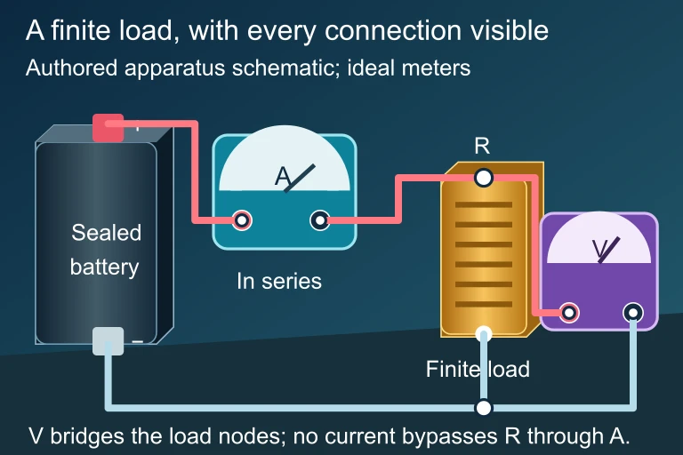
An independently authored battery bench with a sealed battery, finite load, series ammeter and parallel voltmeter, with explicitly joined leads.At a junction with no accumulating charge, the algebraic sum of branch currents is zero. A residual between measured incoming and outgoing currents needs uncertainty information before agreement can be assessed.
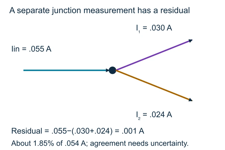
Current-balance residual. An incoming current 0.055 A and outgoing readings 0.030 A and 0.024 A leave a residual of 0.001 A. Deciding whether they agree with charge conservation requires the measurement uncertainties.An incoming current 0.055 A and outgoing readings 0.030 A and 0.024 A leave a residual of 0.001 A. Deciding whether they agree with charge conservation requires the measurement uncertainties.

SECTION 4

Mathematical Framework

The junction rule can be expressed in two equivalent mathematical forms. The choice between them is purely a matter of convenience—they encode exactly the same physical content.

JUNCTION RULE — EQUALITY FORM

ΣIin=ΣIoutΣI_in = ΣI_out

The sum of all currents flowing into a junction equals the sum of all currents flowing out of that junction. This form is intuitive and commonly used for quick analysis.

JUNCTION RULE — ALGEBRAIC FORM

ΣInode=0ΣI_node = 0

Assign a positive sign to currents entering the node and a negative sign to currents leaving (or vice versa, as long as you are consistent). The algebraic sum of all currents at the node is then zero. This form naturally generates the linear equations used in systematic circuit analysis.

Consider a junction with n connected branches. If you assign current variables I₁, I₂, …, In and choose positive directions (arrows) for each branch, the junction rule yields one independent equation. For a circuit with N junctions, you can write N − 1 independent junction equations (the last junction's equation is automatically satisfied if the first N − 1 are). The remaining equations needed to solve for all unknowns come from Kirchhoff's loop rule.

NUMBER OF INDEPENDENT JUNCTION EQUATIONS

Numberofindependentjunctionequations=N−1Number of independent junction equations = N − 1

where N is the total number of junctions in the circuit. This avoids writing redundant equations that provide no new information.

⚠

Handling Assumed Directions

When you guess a current's direction and solve the system, a negative value simply indicates the actual current flows opposite to your assumed arrow. Never go back and re-draw—just report the magnitude and note the corrected direction.

SECTION 5

Multi-Loop Circuit Application

The junction rule truly demonstrates its power when applied to circuits containing multiple loops and branches. In such circuits, a single application of Ohm's law is insufficient because the current differs in each branch. The following diagram shows a two-loop circuit with two batteries and three resistors—a classic configuration on the AP Physics 2 exam.

Two-Loop Circuit with Two JunctionsABR₁R₃R₂ε₁ε₂I₁I₂I₃Junction A: I₁ = I₂ + I₃Junction B: I₂ + I₃ = I₁ (same equation — not independent)
A two-loop circuit with junctions A and B. Current I₁ enters junction A from the left loop, then splits into I₂ (through the middle branch) and I₃ (through the right loop). At junction B the currents recombine. With N = 2 junctions, only N − 1 = 1 independent junction equation exists.

In the circuit above, current I₁ enters junction A from the left branch, then divides: part of it flows downward through R₂ as I₂, and the remainder continues rightward through R₃ as I₃. Applying the junction rule at node A yields the equation I₁ = I₂ + I₃. Although you could also write the junction equation at node B, the result (I₂ + I₃ = I₁) is algebraically identical—confirming that with two junctions, only one independent junction equation is available. To fully solve for I₁, I₂, and I₃ you would need two additional equations from the loop rule, giving a system of three equations in three unknowns.

  1. Step 1 — Label currents: Assign a variable and an assumed direction arrow to each branch.
  2. Step 2 — Identify junctions: Find every point where three or more wires meet.
  3. Step 3 — Write N − 1 junction equations: Set ΣI_in = ΣI_out at each independent junction.
  4. Step 4 — Supplement with loop equations: Use Kirchhoff's loop rule to obtain enough equations to match the number of unknown currents.

SECTION 6

Worked Example

Consider a junction where three wires meet. Wire 1 carries 6.0 A into the junction, Wire 2 carries 2.5 A out of the junction, and Wire 3 carries an unknown current I₃. Determine the magnitude and direction of I₃.

Finding an Unknown Branch Current

  1. 1

    Step 1 — Identify Given Values

    I₁ = 6.0 A (into the junction), I₂ = 2.5 A (out of the junction), and I₃ is unknown.
  2. 2

    Step 2 — Apply the Junction Rule

    Using the equality form: ΣIin = ΣIout. Since I₁ flows in and I₂ flows out, I₃ must flow out (otherwise the junction would have 8.5 A entering and 0 A leaving through that branch, which would not balance). The equation becomes: I₁ = I₂ + I₃.
  3. 3

    Step 3 — Solve for I₃

    6.0 A = 2.5 A + I₃. Subtracting 2.5 A from both sides gives I₃ = 6.0 A − 2.5 A.
    I₃ = 3.5 A, directed out of the junction
  4. 4

    Step 4 — Verify

    Total current in = 6.0 A. Total current out = 2.5 A + 3.5 A = 6.0 A. The junction rule is satisfied; charge is conserved.
    ΣIin = ΣIout = 6.0 A ✓

SECTION 7

Strengths, Limitations & Common Pitfalls

AspectStrengthsLimitations
GeneralityApplies to any circuit topology—series, parallel, or complex networks with any number of branches.Assumes steady-state (DC) conditions; does not directly handle time-varying (AC) circuits without modification.
SimplicityProduces simple linear equations that are straightforward to solve algebraically.For very large networks (many junctions), the number of simultaneous equations grows, making hand calculation tedious.
Direction FlexibilityYou can assume any direction for unknown currents; a negative answer self-corrects the direction.Inconsistent sign conventions across junctions lead to errors; careful bookkeeping is essential.
Physical BasisGrounded in conservation of charge—one of the most fundamental laws of physics.Does not account for displacement current (relevant only at very high frequencies or in capacitor gaps during transients).

Strengths and limitations of the junction rule in practical circuit analysis

⚠️

COMMON EXAM PITFALL

A frequent mistake is writing a junction equation at every node in the circuit, then wondering why the system of equations is under-determined. Remember: in a circuit with N junctions, only N − 1 junction equations are independent. The final junction equation is redundant because it is automatically satisfied if all the others hold—much like how if you know the total score in a basketball game and one team's score, the other team's score is already determined.

SECTION 8

Connection to Advanced Theory

Kirchhoff's junction rule, as presented for DC circuits, is a special case of a more general principle that extends into electrodynamics and beyond. Understanding where the simple rule fits in the broader landscape helps you appreciate both its power and its boundaries.

FeatureKirchhoff's Junction Rule (DC)Continuity Equation (General)
ScopeLumped-element circuits with steady currentsAny charge distribution in space, including time-varying fields
Mathematical FormΣI = 0 at a node (algebraic)∂ρ/∂t + ∇ · J = 0 (partial differential equation)
Key AssumptionNo charge accumulation (∂ρ/∂t = 0)Allows for charge accumulation (e.g., capacitor plates during charging)
Typical CourseAP Physics 2, introductory physicsUpper-division electromagnetism (Griffiths, Jackson)

Kirchhoff's junction rule as a special case of the charge continuity equation

In advanced coursework, you will encounter Maxwell's correction to Ampère's law, which introduces displacement current—a term accounting for changing electric fields in regions like the gap between capacitor plates. When this displacement current is included, the generalized junction rule (continuity equation) holds even during transient processes such as capacitor charging. For the AP Physics 2 exam, however, you can confidently apply ΣIin = ΣIout at every junction in steady-state DC circuits, knowing that this elegant bookkeeping tool is a manifestation of one of nature's most inviolable conservation laws.

SECTION 9

Practice Problems

Question 1: CONCEPTUAL

Which fundamental conservation law is the physical basis for Kirchhoff's junction rule?
  • A. Conservation of energy
  • B. Conservation of electric charge
  • C. Conservation of momentum
  • D. Conservation of angular momentum
Show answer (B)
The correct answer is B. Kirchhoff's junction rule states that the total current entering a node equals the total current leaving it, which is a direct consequence of conservation of electric charge. Charge cannot be created or destroyed, so it cannot accumulate at a junction in a steady-state circuit. Option A (conservation of energy) is the basis for Kirchhoff's loop rule, not the junction rule. Options C and D involve mechanical quantities (momentum and angular momentum) that are not directly relevant to current flow at circuit nodes.

Question 2: BASIC CALCULATION

At a junction in a circuit, three wires meet. Wire 1 carries 4.0 A into the junction and Wire 2 carries 1.5 A into the junction. What is the current in Wire 3?
  • A. 2.5 A, into the junction
  • B. 5.5 A, into the junction
  • C. 5.5 A, out of the junction
  • D. 2.5 A, out of the junction
Show answer (C)
The correct answer is C. Applying ΣI_in = ΣI_out: the total current entering the junction is 4.0 A + 1.5 A = 5.5 A. Since both known currents flow in, Wire 3 must carry the entire 5.5 A out of the junction to conserve charge. Option A (2.5 A in) would mean 8.0 A enters and 0 A leaves. Option B (5.5 A in) would mean 11.0 A enters with no exit path. Option D (2.5 A out) would give only 2.5 A leaving versus 5.5 A entering, violating charge conservation.

Question 3: INTERMEDIATE

Four wires meet at a single junction. Wire A carries 3.0 A into the junction, Wire B carries 5.0 A into the junction, Wire C carries 6.0 A out of the junction, and Wire D carries an unknown current IDI_D. What is the magnitude and direction of IDI_D?
  • A. 2.0 A, out of the junction
  • B. 2.0 A, into the junction
  • C. 8.0 A, out of the junction
  • D. 14.0 A, out of the junction
Show answer (A)
The correct answer is A. Applying the junction rule: ΣI_in = ΣI_out. The total current in is 3.0 A + 5.0 A = 8.0 A. The known current out is 6.0 A. Therefore IDI_D must be 8.0 A − 6.0 A = 2.0 A, directed out of the junction. Option B (2.0 A in) would give 10.0 A entering versus only 6.0 A leaving. Option C (8.0 A out) would mean 14.0 A total leaving versus 8.0 A entering. Option D (14.0 A out) would produce an even larger imbalance. Only 2.0 A outward restores the balance required by charge conservation.

Question 4: APPLIED

4 pts
A student wants to experimentally verify Kirchhoff's junction rule using a circuit with a battery, three resistors (R₁ = 100 Ω, R₂ = 220 Ω, R₃ = 330 Ω) where R₁ is in series with the parallel combination of R₂ and R₃, and three ammeters. The student obtains the following ammeter readings: A₁ = 0.054 A, A₂ = 0.032 A, and A₃ = 0.021 A. (a) Describe how the student should connect the three ammeters to measure the current through each resistor. (b) Identify the junction at which the student should test the rule, and write the expected junction equation in terms of the ammeter readings. (c) Explain one realistic source of experimental error that could cause the ammeter readings to appear not to satisfy the junction rule exactly. (d) Calculate the percent discrepancy from the junction rule prediction and explain what uncertainty information is needed to decide whether the residual is consistent with measurement uncertainty.
Show answer
Point 1 — Ammeter placement (1 pt): Connect each ammeter in series with the resistor whose current it measures: A1 with the main-branch R1, A2 with R2, and A3 with R3. Point 2 — Junction equation (1 pt): At the node where R1 splits into the R2 and R3 branches, I1 = I2 + I3. Point 3 — Measurement error (1 pt): Finite meter resolution or calibration uncertainty can cause measured values to differ from the exact simultaneous currents. Readings taken at different times while circuit conditions change can also disagree. Resistor tolerance, contact resistance and meter loading change actual currents, but do not make simultaneous steady-state currents violate charge conservation. Point 4 — Quantitative analysis (1 pt): A2 + A3 = 0.053 A, giving residual 0.054 − 0.053 = 0.001 A = 1 mA. Percent discrepancy relative to A1 is (0.001/0.054) × 100% = 1.85% ≈ 1.9%. Whether this agrees within experimental uncertainty cannot be decided without the ammeter uncertainties. Compare the 1 mA residual with the combined uncertainty of I1 − I2 − I3; resistor tolerance alone is not the relevant uncertainty bound.

Question 5: CRITICAL THINKING

4 pts
A student examines a complex circuit that has 4 junctions and 6 branches. Each branch carries an unknown current. (a) How many independent junction equations can the student write? Justify your answer. (b) How many additional equations (from the loop rule) are needed to solve for all six unknown currents? Show your reasoning. (c) A classmate claims that the junction rule fails when a capacitor is being charged because current 'enters' one plate but 'doesn't come out' the other side. Evaluate this claim. Does the junction rule truly fail, or is the classmate misunderstanding the situation? Explain your reasoning in terms of the physical quantities involved.
Show answer
Rubric (4 points): Point 1 (Independent junction equations): The number of independent junction equations is N − 1 = 4 − 1 = 3. The last junction equation is automatically satisfied if the first three hold, because any current that enters the circuit through one junction must eventually exit through another, making the last equation linearly dependent. (1 point) Point 2 (Loop equations needed): With 6 unknowns and 3 independent junction equations, the student needs 6 − 3 = 3 independent loop equations. Alternatively, using the formula for independent loops: L = B − N + 1 = 6 − 4 + 1 = 3, where B is the number of branches and N is the number of nodes. (1 point) Point 3 (Evaluating the capacitor claim): The classmate's claim is based on a misunderstanding. The junction rule applies to nodes in the external circuit wiring. Current flows into one plate of the capacitor and simultaneously flows out of the other plate (as charge accumulates on one plate, an equal charge is repelled from the other). In the external circuit, the current entering the capacitor branch equals the current leaving it at any instant, so the junction rule is satisfied at the external nodes. (1 point) Point 4 (Nuanced understanding): Full credit requires noting that while current does not physically cross the capacitor gap, the conduction current in the wire on one side equals the conduction current on the other side during charging. In the more advanced framework, Maxwell introduced displacement current (ε₀ dΦ_E/dt) to account for the changing electric field between the plates, ensuring the generalized form of the junction rule (continuity equation) holds everywhere, including inside the capacitor gap. However, for circuit-level analysis, the simple junction rule remains valid at all external nodes. (1 point)

SUMMARY

Lesson Summary

Summary

Kirchhoff's junction rule states that the total current entering any junction (node) in a circuit equals the total current leaving it: ΣI_in = ΣI_out. This rule is a direct consequence of the conservation of electric charge under steady-state (DC) conditions, which require that no charge accumulates at any point in the circuit.

In a circuit with N junctions, you can write N − 1 independent junction equations; the remaining equations needed to solve for all branch currents come from Kirchhoff's loop rule. When applying the rule, you may freely assume current directions—a negative solution simply means the actual direction is opposite to your assumption. Together, the junction and loop rules form a complete toolkit for analyzing any DC circuit, no matter how complex its topology.

Varsity Tutors • AP Physics 2: Algebra-Based • Kirchhoff's Junction Rule