
SECTION 1
Historical Context & Motivation
Mirrors rank among humanity's oldest optical tools, and their history reveals an evolving understanding of how light interacts with reflective surfaces. Ancient civilizations used polished metals—bronze in Egypt, obsidian in Anatolia—long before anyone articulated a mathematical law of reflection. The Greeks, particularly Euclid around 300 BCE, first formalized the idea that the angle of incidence equals the angle of reflection, laying the groundwork for geometric optics. Yet it took many more centuries before scholars understood how curved mirrors could focus light and produce images at predictable locations.
~300 BCE • Euclid's Catoptrica
~1000 CE • Ibn al-Haytham's Kitāb al-Manāẓir
1663 • Gregory's Reflecting Telescope
1668 • Newton's Reflector
1932 • Modern Mirror Fabrication
The central question that geometric optics answers is deceptively simple: given a mirror of known shape and an object at a known position, where does the image form, and what are its properties? Answering this question requires a systematic framework built on the law of reflection, ray-tracing techniques, and a concise algebraic relationship—the mirror equation. These tools allow physicists and engineers to predict whether an image will be real or virtual, upright or inverted, and magnified or diminished, all from the geometry of the mirror and the object's placement.
SECTION 2
Core Principles & Definitions
Image formation by mirrors rests on a small set of powerful ideas that apply uniformly to plane, concave, and convex mirrors. Before diving into ray diagrams and equations, it is essential to establish the vocabulary and sign conventions used throughout geometric optics. The AP Physics 2 exam uses the standard sign convention in which distances measured on the same side as the incoming light (the object side) are positive, and distances behind the mirror surface are negative. This convention keeps the mirror equation consistent across all mirror types.
Law of Reflection
Real vs. Virtual Images
Focal Point & Focal Length
Magnification
Principal Axis & Center of Curvature
KEY TAKEAWAY
SECTION 3
Ray Diagrams for Concave Mirrors
Ray diagrams are the single most important qualitative tool for understanding image formation. For a concave (converging) mirror, three principal rays originate from the tip of the object: (1) a ray parallel to the principal axis reflects through the focal point F, (2) a ray through the focal point reflects parallel to the axis, and (3) a ray through the center of curvature C reflects back on itself. The intersection of any two of these rays locates the tip of the image. The diagram below illustrates the case where the object is placed beyond the center of curvature, producing a real, inverted, and diminished image between F and C.
The diagram encapsulates the most common AP exam scenario for concave mirrors. When the object distance do exceeds the radius of curvature R, reflected rays converge to form a real image between F and C. Moving the object closer to C causes the image to grow and recede; placing the object between F and C flips this relationship—the image appears beyond C, magnified and still inverted. The critical transition occurs when the object sits exactly at F: reflected rays emerge parallel and no image forms at a finite distance. Inside F, the concave mirror produces a virtual, upright, magnified image behind the mirror surface—exactly the configuration used in makeup and shaving mirrors.
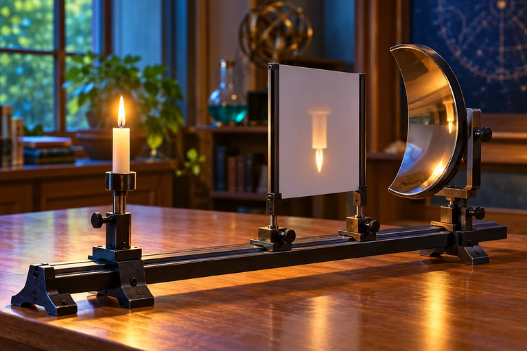 A concave mirror forms a real image where reflected rays converge. When the object is inside the focal length, the reflected rays diverge and their backward extensions locate an upright virtual image.
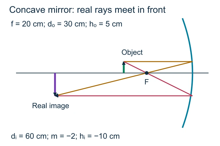 With focal length 20 cm, an object 30 cm in front of the mirror forms a real image 60 cm in front. A 5 cm object gives an inverted 10 cm image.
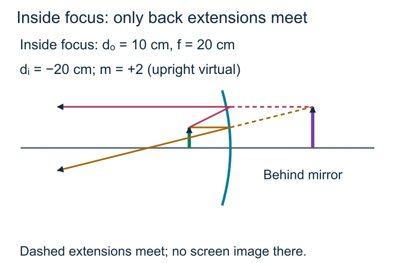 An object 10 cm in front of a concave mirror with f = 20 cm has image distance −20 cm and magnification +2. Only backward extensions meet behind the mirror.
SECTION 4
Mathematical Framework
The quantitative analysis of image formation by spherical mirrors relies on two equations that the AP Physics 2 exam expects you to apply fluently. Both equations emerge from the geometry of similar triangles formed by the principal rays, the principal axis, and the mirror surface. Combined with a consistent sign convention, they predict every measurable property of the image.
MIRROR EQUATION
f = focal length (positive for concave, negative for convex); do = object distance (always positive for real objects); di = image distance (positive for real images in front of mirror, negative for virtual images behind mirror).
LATERAL MAGNIFICATION
m = lateral magnification; hi = image height; ho = object height. |m| > 1 indicates enlargement; |m| < 1 indicates reduction. Positive m → upright image; negative m → inverted image.
FOCAL LENGTH–RADIUS RELATION
R = radius of curvature of the spherical mirror. This relationship holds in the paraxial approximation, where rays strike the mirror close to the principal axis. For a plane mirror, R → ∞ so f → ∞, and the mirror equation yields di = −do (virtual image at equal distance behind the mirror).
Sign Convention Summary
SECTION 5
Image Characteristics by Mirror Type
A thorough understanding of image formation requires knowing how image properties change as the object moves relative to the mirror. The three mirror types—plane, concave, and convex—each have distinct behaviors. A plane mirror always produces a virtual, upright, same-size image (m = +1) located as far behind the surface as the object is in front. A convex mirror always produces a virtual, upright, diminished image regardless of object position, which is why it is used as a wide-angle security or vehicle mirror. The concave mirror is the richest case: its image properties depend critically on where the object is placed relative to F and C.
| Object Position (Concave) | Image Location | Image Type | Size / Orientation |
|---|---|---|---|
| do > R (beyond C) | Between F and C | Real | Diminished, Inverted |
| do = R (at C) | At C | Real | Same size, Inverted |
| f < do < R (between F and C) | Beyond C | Real | Magnified, Inverted |
| do = f (at F) | At infinity (no finite image) | — | — |
| do < f (inside F) | Behind mirror | Virtual | Magnified, Upright |
Summary of concave mirror image properties as a function of object position
AP Exam Tip
SECTION 6
Worked Example
Concave Mirror: Finding Image Position and Characteristics
- 1
Step 1 — Identify Given Values
A concave mirror has a radius of curvature R = 40.0 cm. An object 5.0 cm tall is placed 30.0 cm in front of the mirror. We need to find the image distance di, the magnification m, and the image height hi.R = 40.0 cm → f = R/2 = 20.0 cm; do = 30.0 cm; ho = 5.0 cm - 2
Step 2 — Apply the Mirror Equation
Using 1/f = 1/do + 1/di, we rearrange: 1/di = 1/f − 1/do = 1/20.0 − 1/30.0 = (3 − 2)/60 = 1/60.di = +60.0 cm (positive → real image, in front of mirror) - 3
Step 3 — Calculate Magnification
m = −di / do = −60.0 / 30.0 = −2.0.m = −2.0 (negative → inverted; |m| = 2 → magnified by factor of 2) - 4
Step 4 — Find Image Height
hi = m × ho = (−2.0)(5.0 cm) = −10.0 cm.hi = −10.0 cm (the negative sign confirms the image is inverted) - 5
Step 5 — Interpret the Result
The object was between F (20 cm) and C (40 cm). The image forms at 60.0 cm in front of the mirror—beyond C. It is real (di > 0), inverted (m < 0), and magnified (|m| > 1). This matches the third row of the classification table in Section 5, confirming our calculation.Real, inverted, magnified image at 60.0 cm, height 10.0 cm
SECTION 7
Comparing Mirror Types: Strengths & Limitations
Each mirror type has practical advantages and disadvantages that explain its real-world applications. The AP Physics 2 curriculum expects you to connect these properties to everyday and scientific contexts, from telescopes and solar furnaces to security mirrors and automobile side mirrors.
| Property | Plane Mirror | Concave Mirror | Convex Mirror |
|---|---|---|---|
| Image type | Always virtual | Real or virtual (depends on do) | Always virtual |
| Orientation | Upright (laterally reversed) | Inverted (real) or upright (virtual) | Always upright |
| Magnification | m = +1 always | |m| can be < 1, = 1, or > 1 | 0 < m < 1 always |
| Focal length | f → ∞ | f > 0 (positive) | f < 0 (negative) |
| Common applications | Bathroom mirrors, periscopes | Telescopes, headlights, solar furnaces, shaving/makeup mirrors | Passenger side mirrors, store security mirrors, ATM cameras |
| Key limitation | Cannot project real images; no magnification | Spherical aberration for large apertures; image properties change with do | Image always smaller than object; cannot form real images |
Comprehensive comparison of the three mirror types tested on AP Physics 2
KEY TAKEAWAY
SECTION 8
Connection to Lenses & Advanced Optics
The mirror equation is not an isolated result—it has a direct counterpart in the thin lens equation, which takes the identical algebraic form 1/f = 1/do + 1/di. The analogy between converging lenses and concave mirrors (both have positive f), and between diverging lenses and convex mirrors (both have negative f), runs deep. Mastering the sign conventions and ray-tracing techniques for mirrors provides a transferable framework that applies immediately when the AP Physics 2 curriculum moves to refraction and lenses.
| Feature | Mirrors (Reflection) | Thin Lenses (Refraction) |
|---|---|---|
| Governing equation | 1/f = 1/do + 1/di | 1/f = 1/do + 1/di |
| Converging element | Concave mirror (f > 0) | Converging (convex) lens (f > 0) |
| Diverging element | Convex mirror (f < 0) | Diverging (concave) lens (f < 0) |
| Image side | Same side as object for real images | Opposite side from object for real images |
| Chromatic aberration | None (reflection is independent of wavelength) | Present (index of refraction depends on wavelength) |
| Spherical aberration | Present for large-aperture spherical mirrors | Present for large-aperture spherical lenses |
Mirrors vs. thin lenses: structural parallels and key differences
At a more advanced level, the paraxial approximation underlying the mirror equation breaks down for rays far from the principal axis, leading to spherical aberration—marginal rays focus at a different point than paraxial rays. Parabolic mirrors eliminate this defect entirely, which is why modern telescopes (such as the 6.5-meter primary mirror of the James Webb Space Telescope) use paraboloidal surfaces. While parabolic mirror geometry goes beyond AP Physics 2, understanding why the approximation works—and where it fails—deepens your appreciation for the elegance and limitations of the algebraic model.
SECTION 9
Practice Problems
Question 1: CONCEPTUAL
- A. A real, inverted image forms at the center of curvature.
- B. A virtual, upright, magnified image forms behind the mirror.
- C. No image forms at a finite distance because reflected rays are parallel.
- D. A real, inverted image of the same size forms at the focal point.
Show answer (C)
Question 2: BASIC CALCULATION
- A. −10 cm
- B. +10 cm
- C. −30 cm
- D. +30 cm
Show answer (A)
Question 3: INTERMEDIATE
- A. −2.5
- B. +2.5
- C. +0.40
- D. −0.60
Show answer (B)
Question 4: APPLIED
5 ptsShow answer
Question 5: CRITICAL THINKING
4 ptsShow answer
SUMMARY
Summary
Summary
Image formation by mirrors is governed by the law of reflection and analyzed using ray diagrams and the mirror equation (1/f = 1/do + 1/di). Plane mirrors produce virtual, upright, same-size images. Concave mirrors (f > 0) produce real or virtual images depending on whether the object lies outside or inside the focal point. Convex mirrors (f < 0) always produce virtual, upright, diminished images.
The magnification equation m = −di/do encodes both size ratio and orientation in a single signed quantity. Master the sign conventions (positive f and di on the reflective side; negative behind) and the three principal rays for ray diagrams, and you will be prepared for both the qualitative and quantitative mirror questions that appear on the AP Physics 2 exam.