
SECTION 1
Historical Context & Motivation
The notion that charged objects can influence one another across empty space posed one of the deepest puzzles in the history of physics. In the eighteenth century, Charles-Augustin de Coulomb quantified the force between point charges and demonstrated that it obeys an inverse-square law, much like gravity. Yet a fundamental question remained: how does one charge "know" the other is there? The concept of action at a distance troubled physicists, because it implied instantaneous influence with no mediating mechanism. It was Michael Faraday's revolutionary insight — that charged bodies create an invisible field pervading the surrounding space — that shifted the paradigm from forces acting at a distance to a local field-based description of electromagnetic phenomena.
1785 • Coulomb's Torsion-Balance Experiments
1831 • Faraday Introduces "Lines of Force"
1862 • Maxwell's Field Equations
1909 • Millikan's Oil-Drop Experiment
The central question this lesson addresses is both conceptual and practical: How do we describe the influence a charged object exerts on the space around it, and how can we use that description to predict the force on any other charge placed in that region? By introducing the electric field as an independent physical quantity defined at every point in space, we gain a tool that is far more powerful and general than simply cataloging forces between pairs of charges.
SECTION 2
Core Principles & Definitions
An electric field is a vector quantity that exists at every point in the space surrounding a charged object (the source charge). Operationally, the field at a given location is defined as the electric force per unit positive charge that would be experienced by a small test charge placed there. Crucially, the test charge must be small enough that it does not significantly disturb the source charge distribution. Because the field is a property of the space itself — created by the source — it exists whether or not a test charge is actually present. This is the conceptual leap Faraday made: the field is real, not merely a mathematical convenience.
Electric Field as Force per Charge
Direction Convention
Superposition Principle
Field Lines
KEY TAKEAWAY
SECTION 3
Visualizing Electric Fields
Electric field lines provide one of the most powerful ways to build intuition about the behavior of electric fields. The following diagram illustrates the field line patterns for three foundational configurations: a single positive point charge, a single negative point charge, and an electric dipole (a pair of equal-magnitude but opposite charges). Observe how the density and curvature of the lines encode both the magnitude and direction of the field everywhere in the surrounding space.
Several key features of the diagram deserve attention. For the isolated positive charge on the left, the lines are symmetric and radial; their spacing increases with distance from the charge, reflecting the inverse-square decrease in field magnitude. For the negative charge in the center, the pattern is identical in shape but the arrows point inward, toward the charge. In the dipole configuration on the right, the lines originate on the positive charge and terminate on the negative charge, curving outward and back. Between the charges the field is strong (lines are dense), while far from the dipole the lines become sparse and the configuration increasingly resembles that of a neutral object. Note that field lines never cross — because the electric field has a unique direction at every point, two lines intersecting would imply two different directions, which is physically impossible.
SECTION 4
Mathematical Framework
The quantitative treatment of electric fields connects the conceptual field picture to measurable, calculable quantities. We begin with the operational definition of the electric field, then specialize to the important case of the field produced by a point charge, and finally state the superposition principle in mathematical form.
DEFINITION OF ELECTRIC FIELD
E⃗ = electric field vector (N/C or V/m); F⃗ = electrostatic force on the test charge (N); q₀ = positive test charge (C). The test charge must be vanishingly small so as not to perturb the source distribution.
FIELD OF A POINT CHARGE
k = Coulomb's constant ≈ 8.99 × 10⁹ N·m²/C²; Q = source charge (C); r = distance from the source charge to the field point (m). The field points radially outward if Q > 0 and radially inward if Q < 0.
SUPERPOSITION OF FIELDS
The net electric field at any point is the vector sum of the fields produced by each individual source charge. Because this is a vector addition, you must resolve components along orthogonal axes and sum them separately before recombining.
FORCE ON A CHARGE IN AN EXTERNAL FIELD
Once the electric field is known, the force on any charge q placed in that field is simply the charge multiplied by the field vector. If q is negative, the force is opposite to the field direction.
AP Exam Tip
SECTION 5
Common Field Configurations
Beyond isolated point charges, the AP Physics 2 curriculum requires familiarity with the electric field patterns of several common charge configurations. Understanding these canonical cases — the uniform field between parallel plates, the radial field of a charged sphere, and the field of continuous charge distributions — builds the physical intuition needed to analyze more complex scenarios. The diagram below depicts the uniform field between two large parallel conducting plates, one of the most frequently tested setups on the exam.
| Configuration | Field Magnitude | Key Feature |
|---|---|---|
| Point Charge | E = kQ / r² | Radial symmetry; decreases with inverse square of distance |
| Parallel Plates | E = V / d = σ / ε₀ | Uniform field between plates; E is independent of position |
| Conducting Sphere (outside) | E = kQ / r² (r > R) | Behaves as if all charge were at center; zero field inside |
| Insulating Sphere (inside) | E = kQr / R³ (r < R) | Field increases linearly with r for uniform charge density |
Table 1. Summary of electric field expressions for common charge configurations tested on AP Physics 2.
The parallel-plate configuration is especially important because it produces a uniform electric field — one whose magnitude and direction are the same everywhere between the plates (neglecting edge effects). This simplification makes it the go-to setup for problems involving charged-particle motion, energy arguments, and connections to electric potential. The relationship E = V/d, where V is the potential difference between the plates and d is the plate separation, appears repeatedly on both the multiple-choice and free-response sections of the AP exam.
SECTION 6
Worked Example: Superposition of Two Point Charges
Consider two point charges arranged along the x-axis. Charge q₁ = +4.0 μC is located at the origin, and charge q₂ = −9.0 μC is located at x = 0.30 m. We wish to find the net electric field at point P, located on the x-axis at x = 0.10 m (between the two charges).
Net Electric Field at Point P
- 1
Step 1 — Identify given values and geometry
q₁ = +4.0 × 10⁻⁶ C at x = 0. q₂ = −9.0 × 10⁻⁶ C at x = 0.30 m. Point P is at x = 0.10 m. The distance from q₁ to P is r₁ = 0.10 m. The distance from q₂ to P is r₂ = 0.30 − 0.10 = 0.20 m. Coulomb's constant k = 8.99 × 10⁹ N·m²/C². - 2
Step 2 — Calculate the magnitude of E⃗₁ at P
Using E = kQ / r², we find E₁ = (8.99 × 10⁹)(4.0 × 10⁻⁶) / (0.10)² = (8.99 × 10⁹)(4.0 × 10⁻⁶) / 0.01.E₁ = 3.60 × 10⁶ N/C - 3
Step 3 — Determine the direction of E⃗₁ at P
Since q₁ is positive, the field it produces at P points away from q₁ — that is, in the +x direction. - 4
Step 4 — Calculate the magnitude of E⃗₂ at P
E₂ = (8.99 × 10⁹)(9.0 × 10⁻⁶) / (0.20)² = (8.99 × 10⁹)(9.0 × 10⁻⁶) / 0.04.E₂ = 2.02 × 10⁶ N/C - 5
Step 5 — Determine the direction of E⃗₂ at P
Since q₂ is negative, the field it produces at P points toward q₂ — that is, in the +x direction (P is to the left of q₂, and the field points from P toward the negative charge). - 6
Step 6 — Apply superposition
Both E⃗₁ and E⃗₂ point in the +x direction at P. Therefore E_net = E₁ + E₂ = 3.60 × 10⁶ + 2.02 × 10⁶.E_net = 5.62 × 10⁶ N/C in the +x direction
Why Both Fields Point the Same Way
SECTION 7
Electric Field vs. Gravitational Field
Drawing explicit comparisons between the electric field and the gravitational field deepens understanding of both concepts. Both fields obey inverse-square laws for point-like sources, and both can be described using a field model that eliminates the need for action at a distance. However, significant differences exist — most notably that electric charge comes in two signs (producing both attractive and repulsive interactions) while gravitational mass is always positive (gravity is purely attractive). The table below highlights the most instructive parallels and contrasts.
| Feature | Electric Field | Gravitational Field |
|---|---|---|
| Source | Electric charge (positive or negative) | Mass (always positive) |
| Force Law | F = kq₁q₂ / r² (Coulomb's law) | F = Gm₁m₂ / r² (Newton's law of gravitation) |
| Field Definition | E⃗ = F⃗ / q₀ (force per unit positive charge) | g⃗ = F⃗ / m₀ (force per unit mass) |
| Nature of Force | Attractive or repulsive (depends on sign of charges) | Always attractive |
| Relative Strength | Enormously stronger — dominates at atomic and molecular scales | Extremely weak — only significant for large (planetary-scale) masses |
| Shielding | Possible with conductors (Faraday cage) | Not possible — no known gravitational shielding |
Table 2. Parallel structure of the electric and gravitational fields.
KEY TAKEAWAY
SECTION 8
Connection to Electric Potential & Gauss's Law
The electric field does not exist in isolation within the theoretical framework of electromagnetism; it connects intimately to other key quantities you will encounter in AP Physics 2 and beyond. Two of the most important connections are to electric potential (voltage) and to Gauss's law. Understanding how the electric field relates to these concepts transforms the field from a standalone idea into a node in a rich conceptual network.
| Concept | Relationship to Electric Field | Why It Matters |
|---|---|---|
| Electric Potential (V) | E = −ΔV / Δx (uniform field); the field points from high potential to low potential | Allows energy-based analysis; potential is a scalar (easier to sum than vectors) |
| Gauss's Law | Φ_E = ∮E⃗ · dA⃗ = Q_enc / ε₀ | Relates the total electric flux through a closed surface to the enclosed charge; powerful for symmetric geometries |
| Equipotential Surfaces | E⃗ is always perpendicular to equipotential surfaces | Visual tool for mapping fields; no work is done moving a charge along an equipotential |
| Conductors in Equilibrium | E⃗ = 0 inside; E⃗ is perpendicular to the surface outside | Explains shielding, charge redistribution, and the behavior of Faraday cages |
Table 3. How the electric field connects to other key topics in electrostatics.
Looking forward, the field concept extends naturally to time-varying situations: a changing magnetic field produces an electric field (Faraday's law of induction), and a changing electric field produces a magnetic field (Ampère–Maxwell law). Together, these relationships form the backbone of Maxwell's equations, which unify all of classical electromagnetism and predict the existence of electromagnetic waves. The static electric field you are studying now is the foundation upon which this entire edifice rests.
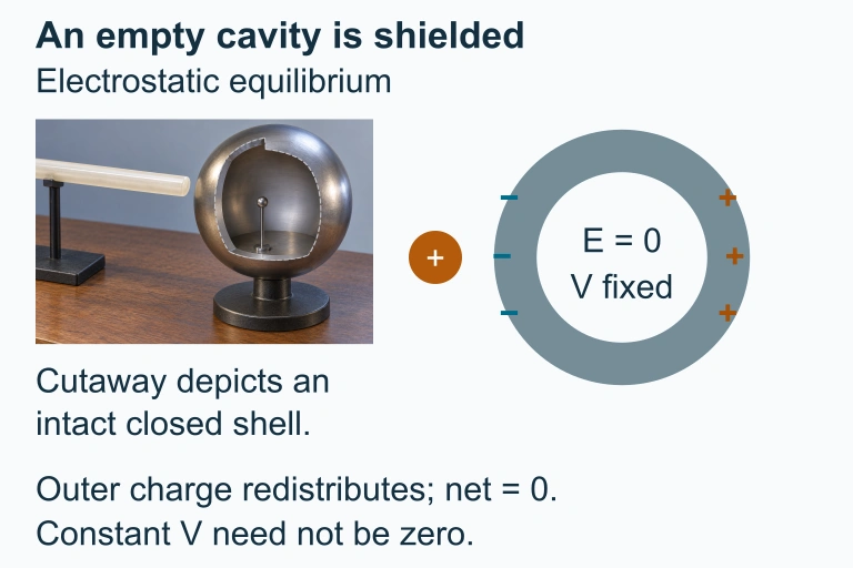 An external charge redistributes charge on a neutral conductor. In electrostatic equilibrium an empty closed cavity has zero electric field and constant potential, which need not be zero.
SECTION 9
Practice Problems
Question 1: CONCEPTUAL
- A. Directed from one charge toward the other with a nonzero magnitude
- B. Zero, because the fields from the two charges cancel
- C. Perpendicular to the line connecting the charges with a nonzero magnitude
- D. Directed outward from both charges, doubling the field strength
Show answer (B)
Question 2: BASIC CALCULATION
- A. 0.10 m
- B. 0.50 m
- C. 1.0 m
- D. 3.0 m
Show answer (C)
Question 3: INTERMEDIATE
- A. x = 0.10 m
- B. x = 0.15 m
- C. x = 0.20 m
- D. x = 0.30 m
Show answer (C)
Question 4: APPLIED
5 ptsShow answer
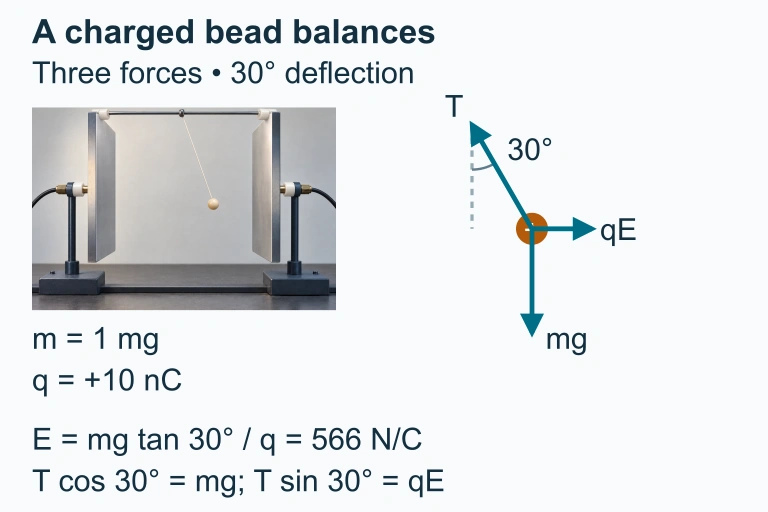 At equilibrium the positive bead's electric force balances the horizontal component of tension, while gravity balances its vertical component.
Question 5: CRITICAL THINKING
4 ptsShow answer
SUMMARY
Electric Fields — Summary
Summary
The electric field is a vector quantity defined at every point in space as the force per unit positive test charge: E⃗ = F⃗/q₀. For a point charge, the field magnitude obeys E = kQ/r², decreasing with the inverse square of distance and pointing radially outward for positive Q, inward for negative Q. When multiple charges are present, the superposition principle states that the net field is the vector sum of the individual fields. Electric field lines provide a powerful visual tool: they begin on positive charges, end on negative charges, never cross, and their density encodes the field magnitude.
The parallel-plate configuration produces a uniform electric field (E = V/d) between the plates, making it the standard setup for problems involving charged-particle motion and connections to electric potential. The relationship F⃗ = qE⃗ allows you to predict the force on any charge once the field is known. At a deeper level, the electric field connects to Gauss's law and to equipotential surfaces, forming the conceptual backbone of electrostatics and pointing the way toward the full electromagnetic theory of Maxwell.