
SECTION 1
Historical Context & Motivation
The study of electricity progressed from curious parlor demonstrations with static charge to the systematic science of electric current over the course of roughly two centuries. Early investigators like Benjamin Franklin recognized that charge could move through conductors, but it was not until the invention of a reliable source of sustained charge flow that quantitative investigation became possible. The development of the voltaic pile in 1800 provided the first continuous source of electrical energy, enabling researchers to study the steady movement of charge through wires and solutions. Each subsequent advance — from Ohm's empirical law to Ampère's precise measurements — deepened our understanding of how and why charge carriers drift in response to an applied electric field, ultimately forming the theoretical backbone of modern circuit analysis.
1745 • The Leyden Jar
1800 • Volta's Pile
1820 • Ørsted & Ampère
1827 • Ohm's Law
1897 • Discovery of the Electron
Despite these breakthroughs, the fundamental question at the heart of circuit physics remained: how do we precisely quantify the rate at which charge flows through a conductor, and what microscopic properties of the material govern that rate? Answering this question requires a clear definition of electric current alongside a model connecting macroscopic measurements to the behavior of individual charge carriers. The sections that follow build this framework from the ground up, equipping you to analyze any circuit on the AP Physics 2 exam.
SECTION 2
Core Principles & Definitions
Electric current is fundamentally a measure of how much charge passes a given cross-section of a conductor per unit time. Although it may seem straightforward, several conceptual subtleties distinguish a rigorous understanding from a surface-level one. The following core ideas form the foundation you will apply throughout the study of electric circuits.
Definition of Current
Conventional vs. Electron Current
Drift Velocity
Current Density
Conditions for Steady Current
KEY TAKEAWAY
SECTION 3
Visual Explanation — Charge Flow in a Conductor
The diagram above captures the essential physics of current flow in a metal. When a battery maintains a potential difference across the wire, an internal electric field E develops, directed from the positive terminal toward the negative terminal. This field exerts a force on each free electron (F = qE), accelerating it briefly before it collides with a lattice ion and loses its directed kinetic energy. The net effect of these countless acceleration-and-collision cycles is a small, steady drift velocity superimposed on the electrons' much larger random thermal velocities. Although individual electrons meander chaotically, their average displacement per unit time is directed opposite to E, producing a measurable macroscopic current. Notice that conventional current I points in the same direction as E — from high to low potential — even though the physical carriers drift the other way.
SECTION 4
Mathematical Framework
The mathematical description of electric current bridges two scales: the macroscopic measurement made by an ammeter and the microscopic motion of charge carriers inside the conductor. On the AP Physics 2 exam, you are expected to use the defining equation of current, the drift velocity model, and Ohm's law fluently. Each equation below is accompanied by variable definitions and a physical interpretation.
DEFINITION OF CURRENT
I = electric current (A); ΔQ = net charge passing through a cross-section (C); Δt = elapsed time (s). This equation states that current equals the rate of charge flow. For a steady current, Q = I × t.
DRIFT VELOCITY MODEL
n = number density of free charge carriers (m⁻³); A = cross-sectional area of the conductor (m²); vd = drift velocity (m/s); q = magnitude of the charge on each carrier (C). This microscopic model connects the collective behavior of charge carriers to the macroscopic current: a larger density, wider wire, or faster drift each increase I.
OHM'S LAW
V = potential difference across a resistor (V); I = current through the resistor (A); R = resistance (Ω). Ohm's law is an empirical relation valid for ohmic materials — those whose resistance remains constant over a range of applied voltages. Non-ohmic devices (diodes, LEDs) do not obey this linear relationship.
CURRENT DENSITY
J = current density (A/m²). Current density is useful when analyzing conductors of non-uniform cross-section: at a narrower region, J increases even though I remains constant (conservation of charge), meaning vd must increase in that segment.
AP Exam Tip
SECTION 5
Detailed Breakdown — The Drift Velocity Model
A deeper appreciation of the drift velocity equation I = nAvdq reveals how each factor independently controls the magnitude of the current. The diagram below illustrates a thought experiment: a cylindrical segment of wire through which charge carriers drift at constant velocity during a time interval Δt.
| Variable | Symbol & Units | Typical Value (Cu wire) | Effect on I |
|---|---|---|---|
| Number density | n (m⁻³) | 8.5 × 10²⁸ | I ∝ n — more carriers, more current |
| Cross-sectional area | A (m²) | ≈ 3.3 × 10⁻⁶ (12 AWG) | I ∝ A — wider wire, more current |
| Drift velocity | (m/s) | ≈ 2.3 × 10⁻⁴ (at 10 A) | I ∝ — stronger field, faster drift |
| Carrier charge | q (C) | 1.6 × 10⁻¹⁹ | Fixed for electrons in metals |
Parameters of the drift velocity model for a standard 12 AWG copper wire
An important consequence of conservation of charge is that the current must be the same at every cross-section of a single, unbranched wire. If the wire narrows, the cross-sectional area A decreases, so the drift velocity vd must increase proportionally to keep I = nAvdq constant. This is the electrical analogue of the continuity equation in fluid dynamics: just as water speeds up when a pipe narrows, electrons accelerate through constrictions in a conductor.
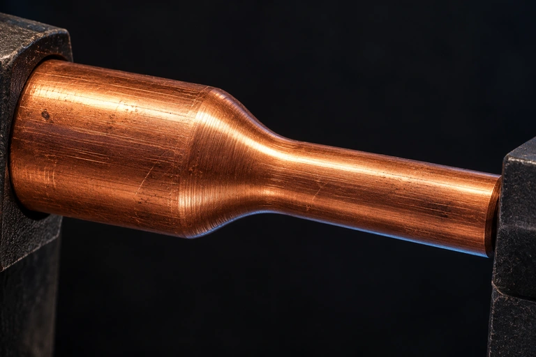 The continuous copper neck is a material illustration. For the separately specified model, the area falls from 2 to 1 mm² while current remains 1 A, so electron drift speed doubles. Conventional current and net electron drift have opposite directions.
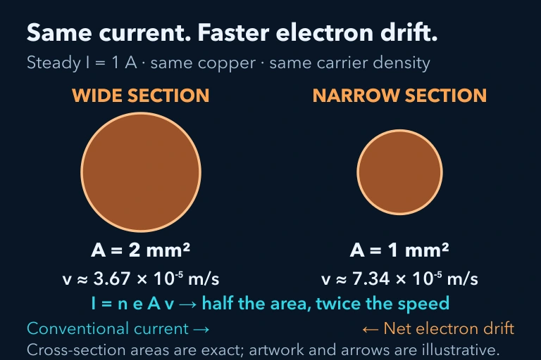 I=1 A, n=8.5×10^28 m^-3, areas 2/1 mm² yieldvd 3.67×10^-5/7.34×10^-5 m/s; electron drift opposite conventional current.
SECTION 6
Worked Example — Calculating Drift Velocity
The following problem demonstrates how to combine the definition of current with the drift velocity model to find the speed at which electrons travel through a household wire — a classic AP Physics 2 question type.
Drift Velocity in a 14 AWG Copper Wire
- 1
Step 1 — Identify Given Values
A 14 AWG copper wire carries a current of I = 5.0 A. The wire has a cross-sectional area A = 2.08 × 10⁻⁶ m². Copper has a free-electron number density of n = 8.5 × 10²⁸ m⁻³, and the electron charge magnitude is q = 1.6 × 10⁻¹⁹ C. We need to find the drift velocity vd. - 2
Step 2 — Select the Appropriate Equation
The drift velocity model relates all the given quantities: I = nAvdq. Solving for vd gives: vd = I / (nAq). - 3
Step 3 — Substitute and Compute
vd = 5.0 / (8.5 × 10²⁸ × 2.08 × 10⁻⁶ × 1.6 × 10⁻¹⁹). First, compute the denominator: 8.5 × 10²⁸ × 2.08 × 10⁻⁶ = 1.768 × 10²³. Then multiply by q: 1.768 × 10²³ × 1.6 × 10⁻¹⁹ = 2.829 × 10⁴. Finally, vd = 5.0 / 2.829 × 10⁴.≈ 1.77 × 10⁻⁴ m/s ≈ 0.18 mm/s - 4
Step 4 — Interpret the Result
The drift velocity is astonishingly small — less than 0.2 millimeters per second. This means an individual electron would take over 90 minutes to traverse just one meter of wire. Yet the current begins flowing almost instantaneously when the switch closes because the electric field propagates at nearly the speed of light, setting all electrons in motion simultaneously. - 5
Step 5 — Verify Units and Reasonableness
Units check: [A] / ([m⁻³][m²][C]) = [C/s] / [m⁻¹ × C] = [m/s] ✓. The order of magnitude (10⁻⁴ m/s) matches the standard reference value for copper at moderate currents, confirming our answer is physically reasonable.
SECTION 7
DC vs. AC — Comparing Current Types
Electric current comes in two fundamental flavors: direct current (DC), in which the charge carriers flow steadily in one direction, and alternating current (AC), in which they oscillate back and forth periodically. The AP Physics 2 curriculum focuses almost exclusively on DC circuits, but understanding the distinction is essential for connecting classroom physics to the real world and for answering conceptual questions about current behavior.
| Property | Direct Current (DC) | Alternating Current (AC) |
|---|---|---|
| Direction of flow | Unidirectional — carriers drift in one direction continuously | Reverses periodically, typically sinusoidally at 60 Hz (US) or 50 Hz (EU) |
| Common sources | Batteries, solar cells, DC power supplies | Wall outlets, generators, transformers |
| Voltage behavior | Constant (ideally); graph is a horizontal line | Varies sinusoidally between +V_peak and −V_peak |
| Typical applications | Electronics, sensors, low-voltage circuits | Power transmission, household appliances, industrial motors |
| AP Physics 2 relevance | Primary focus | Conceptual awareness; not tested quantitatively |
Comparison of direct and alternating current characteristics
KEY TAKEAWAY
SECTION 8
Connection to Advanced Theory — Non-Ohmic Behavior & Microscopic Models
The simple relationship V = IR works beautifully for resistors and metallic conductors at constant temperature, but the real world is filled with devices whose resistance varies with applied voltage, temperature, or illumination. Understanding where Ohm's law breaks down enriches your conceptual toolkit and connects AP-level circuit physics to the more sophisticated models encountered in college electromagnetism and solid-state physics.
| Aspect | AP Physics 2 (Ohmic Model) | Advanced / College Physics |
|---|---|---|
| Current–voltage relationship | Linear: I = V/R with constant R | Nonlinear: R depends on V, T, or other parameters |
| Microscopic model | Drude free-electron model; constant drift velocity per unit field | Band theory; Fermi–Dirac statistics; quantum tunneling in junctions |
| Temperature dependence | Assumed negligible or qualitatively noted | R(T) modeled with temperature coefficients; superconductivity at T ≈ 0 K |
| Example devices | Ideal resistors, uniform wires | Diodes, LEDs, thermistors, transistors, photocells |
| Current density formulation | J = σE (constant conductivity σ) | J = σ(E, T, n)E — conductivity is a function of field, temperature, and carrier concentration |
How the current model evolves from AP to advanced physics
On the AP exam, you may encounter qualitative questions about non-ohmic devices — for example, a graph of I vs. V for a light bulb that curves upward because resistance increases as the filament heats. You should be able to interpret such graphs and explain why the slope (1/R) changes. These questions test conceptual reasoning rather than computation and serve as a bridge to the richer physics of semiconductors and quantum materials you will encounter in future courses.
SECTION 9
Practice Problems
Question 1: CONCEPTUAL
- A. The electrons near the switch travel at the speed of light to the lamp.
- B. The electric field established by the battery propagates through the wire at nearly the speed of light, causing all free electrons to begin drifting almost simultaneously.
- C. The electrons were already moving at high speed due to thermal energy, and the switch merely redirects that motion.
- D. Current only appears to propagate quickly because the lamp's filament has very low thermal inertia.
Show answer (B)
Question 2: BASIC CALCULATION
- A. 0.21 C
- B. 4.7 C
- C. 48 C
- D. 480 C
Show answer (C)
Question 3: INTERMEDIATE
- A. 2.7 × 10⁻⁴ m/s
- B. 1.1 × 10⁻⁴ m/s
- C. 4.3 × 10⁻³ m/s
- D. 6.8 × 10⁻⁵ m/s
Show answer (A)
Question 4: APPLIED
4 ptsShow answer
Question 5: CRITICAL THINKING
4 ptsShow answer
SUMMARY
Summary — Electric Current
Summary
Electric current (I) is the rate at which charge flows through a conductor, defined by I = ΔQ / Δt and measured in amperes. At the microscopic level, current arises from an enormous number of charge carriers moving at a very small drift velocity, related to macroscopic current by I = nAv_d q. Conventional current flows from high to low potential (the direction positive charges would move), which is opposite to the actual electron drift in metals.
For ohmic materials, Ohm's law (V = IR) provides a linear relationship between voltage and current, enabling straightforward circuit analysis. A steady DC current requires a closed loop and a sustained potential difference. Key exam skills include computing current from charge and time, calculating drift velocity from the microscopic model, and reasoning about how changes in wire geometry or applied voltage affect current. Understanding these principles lays the groundwork for analyzing resistors in series and parallel, Kirchhoff's rules, and power dissipation — the next major topics in the electric circuits unit.