

SECTION 1
Historical Context & Motivation
Real-world electrical systems—from the wiring inside your phone to the power grid feeding your home—almost never consist of purely series or purely parallel arrangements. Instead, they combine both topologies into what engineers and physicists call compound (or combination) circuits. Understanding how to analyze these networks required centuries of foundational work in electrostatics, current flow, and energy conservation, culminating in the elegant circuit laws we rely on today.
1800 • Volta's Pile
1827 • Ohm's Law Published
1845 • Kirchhoff's Circuit Laws
1883 • Edison's DC Power Grid
The central question this lesson addresses is: given a circuit where resistors appear in both series and parallel groupings, how do we systematically find the equivalent resistance, the current through each element, and the voltage drop across each element? Mastering this technique is essential for AP Physics 2, where compound circuits appear regularly in both MCQ and FRQ contexts.
SECTION 2
Core Principles & Definitions
Before tackling compound circuits, you need a firm grasp of the rules governing the two fundamental resistor configurations and the conservation laws that bind every circuit together. The following principles form the analytical toolkit you will apply repeatedly throughout this lesson.
Series Resistors
Parallel Resistors
Kirchhoff's Junction Rule
Kirchhoff's Loop Rule
Compound (Combination) Circuit
SECTION 3
Visual Explanation — Anatomy of a Compound Circuit
The diagram above illustrates the most common type of compound circuit you will encounter on the AP exam. Notice how the current has only one path through R₁, making it a series element. At node A the current forks: some flows through R₂ and the rest through R₃. Because R₂ and R₃ share nodes A and B, they form a parallel sub-network. The strategy is to reduce the parallel pair to a single equivalent resistance, then add that equivalent in series with R₁ to obtain the total circuit resistance.
SECTION 4
Mathematical Framework
The analysis of compound circuits rests on three equations used in combination: Ohm's law, the series resistance formula, and the parallel resistance formula. You will apply these iteratively—first inward (reducing sub-networks) then outward (distributing current and voltage).
OHM'S LAW
V = potential difference (V), I = current (A), R = resistance (Ω). Applies to any single resistor or any equivalent resistance.
SERIES EQUIVALENT RESISTANCE
Elements in series carry the same current. The total resistance is always greater than the largest individual resistance.
PARALLEL EQUIVALENT RESISTANCE
Elements in parallel share the same voltage. The equivalent resistance is always less than the smallest individual resistance. For exactly two resistors: Rparallel = (R₁ × R₂) / (R₁ + R₂).
POWER DISSIPATED
P = power (W). Any of these three forms may be convenient depending on which quantities are known for a given element.
SECTION 5
Step-by-Step Reduction Strategy
The general procedure for solving any compound circuit can be summarized in two phases: reduce inward (simplify sub-networks to find total resistance and total current) and expand outward (distribute voltages and currents back to individual elements). The diagram below visualizes this two-phase approach applied to a three-resistor compound circuit.
- Identify all series and parallel sub-groups by tracing current paths from the battery.
- Replace each identified sub-group with its equivalent resistance, starting from the innermost group.
- Repeat until a single equivalent resistance remains; apply Ohm's law to find total current.
- Expand outward: use Ohm's law and Kirchhoff's rules to find voltage and current for each original element.
- Verify that branch currents sum correctly at junctions and voltage drops sum to zero around every loop.
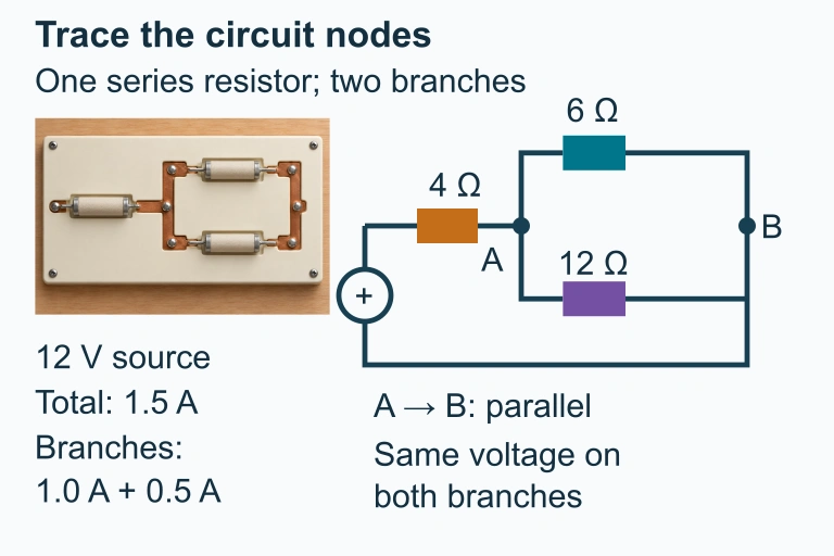 A series resistor leads to two parallel branches sharing nodes A and B. The companion shows a separate simple-circuit preset.
SECTION 6
Worked Example
Consider the circuit shown in Section 3: a 12 V battery connected to R₁ = 4 Ω in series with a parallel combination of R₂ = 6 Ω and R₃ = 12 Ω. Find the equivalent resistance, total current, voltage across each resistor, current through each resistor, and power dissipated in each resistor.
Worked example
- 1
Step 1 — Find the Parallel Equivalent of R₂ and R₃
R₂ and R₃ share nodes A and B, so they are in parallel. Using the two-resistor shortcut: R23 = (R₂ × R₃) / (R₂ + R₃) = (6 × 12) / (6 + 12) = 72 / 18.R₂₃ = 4 Ω - 2
Step 2 — Find the Total Equivalent Resistance
R₁ is in series with R₂₃. For series resistors: Rtotal = R₁ + R₂₃ = 4 + 4.R_total = 8 Ω - 3
Step 3 — Find the Total Current
Apply Ohm's law to the entire circuit: Itotal = ε / Rtotal = 12 / 8.I_total = 1.5 A - 4
Step 4 — Voltage Drop Across R₁
Since R₁ is in series, it carries the full 1.5 A. V₁ = Itotal × R₁ = 1.5 × 4.V₁ = 6 V - 5
Step 5 — Voltage Across the Parallel Pair
By Kirchhoff's loop rule, the remaining voltage appears across the parallel combination: V23 = ε − V₁ = 12 − 6. This is also V₂ = V₃ because parallel elements share the same voltage.V₂ = V₃ = 6 V - 6
Step 6 — Branch Currents in the Parallel Pair
Apply Ohm's law to each branch: I₂ = V₂ / R₂ = 6 / 6 = 1.0 A, and I₃ = V₃ / R₃ = 6 / 12 = 0.5 A. Check: I₂ + I₃ = 1.0 + 0.5 = 1.5 A = Itotal. ✓I₂ = 1.0 A, I₃ = 0.5 A - 7
Step 7 — Power Dissipated
P₁ = I₁² × R₁ = (1.5)² × 4 = 9 W. P₂ = I₂² × R₂ = (1.0)² × 6 = 6 W. P₃ = I₃² × R₃ = (0.5)² × 12 = 3 W. Total power = 9 + 6 + 3 = 18 W, which matches Pbattery = ε × I = 12 × 1.5 = 18 W. ✓P₁ = 9 W, P₂ = 6 W, P₃ = 3 W
SECTION 7
Series vs. Parallel vs. Compound — A Comparison
| Property | Pure Series | Pure Parallel | Compound |
|---|---|---|---|
| Current | Same through all elements | Splits at junctions | Same in series sections; splits in parallel sections |
| Voltage | Divides proportional to R | Same across all branches | Divides in series sections; shared in parallel sections |
| R_eq | R₁ + R₂ + … | (1/R₁ + 1/R₂ + …)⁻¹ | Combine sub-groups iteratively |
| Effect of removing one R | Entire circuit breaks (open) | Other branches unaffected | Depends on location; may affect only a sub-branch or the whole circuit |
| Typical use | Voltage dividers, daisy-chained holiday lights | Household outlets, car battery loads | Most real circuits: computers, power grids, lab setups |
Comparison of series, parallel, and compound circuit properties
SECTION 8
Connection to Advanced Circuit Theory
The reduction technique you have learned works beautifully for ladder networks—circuits that can be fully decomposed into nested series-parallel groups. However, some circuits (such as the Wheatstone bridge or more general mesh topologies) cannot be reduced by simple series-parallel substitution. For those, physicists and engineers turn to Kirchhoff's loop and junction equations written as a system of simultaneous linear equations, or to more advanced methods like mesh analysis and nodal analysis covered in college-level circuit theory.
| Feature | AP Physics 2 (This Lesson) | College Circuit Theory |
|---|---|---|
| Circuit types | Series, parallel, series-parallel compound | Any topology including bridge and mesh networks |
| Primary method | Series-parallel reduction + Ohm's law | Mesh/nodal analysis, Thévenin/Norton equivalents |
| Components | Ideal resistors, ideal battery (no internal resistance on most problems) | Resistors, capacitors, inductors, dependent sources, non-ideal batteries |
| Math required | Algebra (fractions, reciprocals) | Linear algebra, differential equations (for AC and transients) |
AP-level compound circuits vs. college-level circuit theory
Even so, the intuition you build here—recognizing series and parallel relationships, applying conservation of charge at junctions and conservation of energy around loops—carries directly into every future circuit course. Many advanced methods are simply efficient bookkeeping systems for the same Kirchhoff's laws you already know.
SECTION 9
Practice Problems
Question 1: CONCEPTUAL
- A. The 10 Ω resistor carries a larger current and has a larger voltage drop than the 20 Ω resistor.
- B. The 10 Ω resistor carries the same current and has the same voltage drop as the 20 Ω resistor.
- C. The 10 Ω resistor carries a smaller current than the 20 Ω resistor but has a larger voltage drop.
- D. The 10 Ω resistor carries a larger current than the 20 Ω resistor but has a smaller voltage drop.
Show answer (D)
Question 2: BASIC CALCULATION
- A. 1.5 A
- B. 2.0 A
- C. 3.0 A
- D. 4.0 A
Show answer (B)
Question 3: INTERMEDIATE
- A. 1.5 W
- B. 3.0 W
- C. 4.5 W
- D. 6.0 W
Show answer (D)
Question 4: APPLIED
Show answer
Question 5: CRITICAL THINKING
Show answer
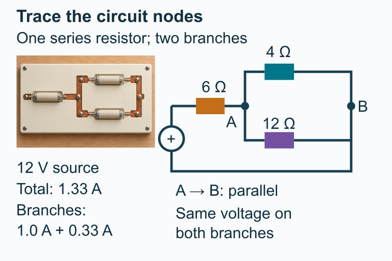 Separate simple-circuit preset: 6 Ω in series with 4 Ω and 12 Ω branches.
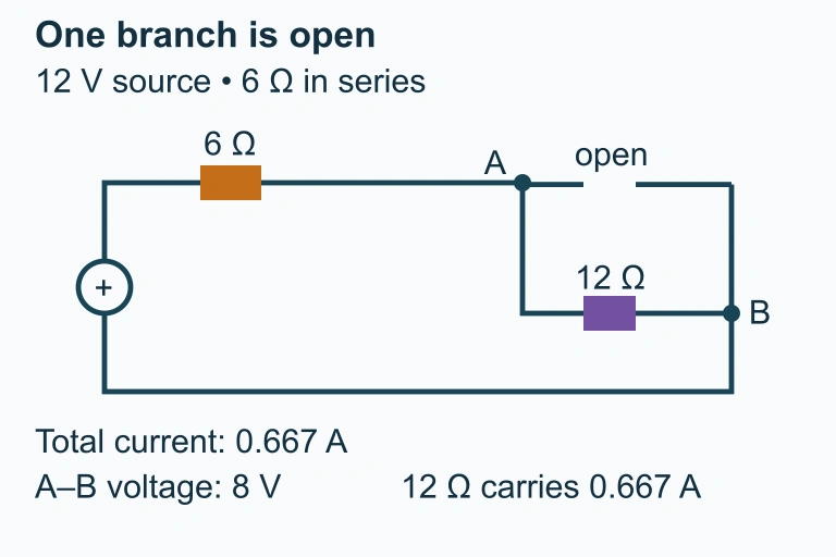 Opening the 4 Ω branch leaves the 12 Ω branch carrying current. A bridge between A and B bypasses both parallel resistors while the 6 Ω series resistor remains.
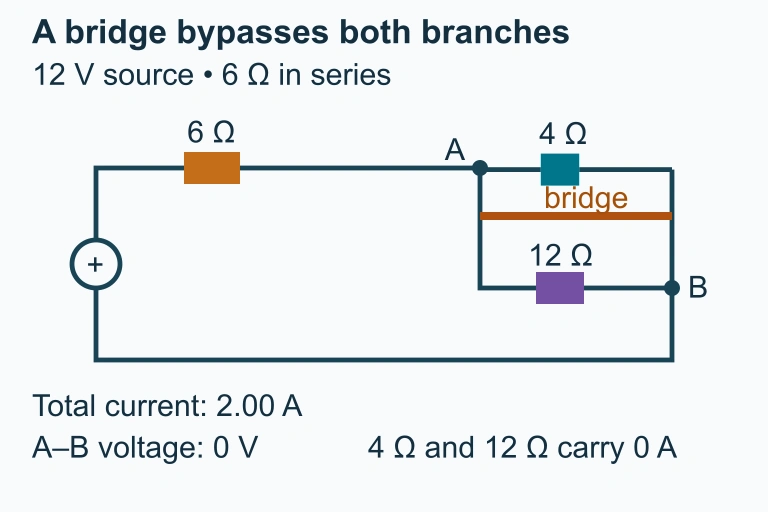 A bridge across nodes A and B bypasses both parallel resistors.