

SECTION 1
Historical Context & Motivation
The ability to store electric charge fascinated natural philosophers long before anyone understood electricity at the atomic level. Early experimenters discovered that certain arrangements of conductors could "hold" charge and release it in dramatic sparks, hinting at a deeper relationship between geometry, materials, and the electric field. The capacitor — originally called a "condenser" — evolved from a laboratory curiosity into one of the most essential components in modern electronics, from camera flashes to cardiac defibrillators.
1745 • The Leyden Jar
1775 • Volta's Electrophorus
1837 • Faraday & Dielectrics
1861 • Maxwell's Field Theory
The central question these discoveries address is remarkably practical: How can we store electrical energy without a chemical reaction, and how does the geometry of conductors and the choice of insulator govern that storage? Answering this question leads directly to the physics of capacitance, electric fields, and potential difference — core topics in AP Physics 2.
SECTION 2
Core Principles & Definitions
A capacitor is any system of two conductors carrying equal and opposite charges, separated by an insulating region (which may simply be a vacuum). When a voltage source is connected across the conductors, charge migrates until the potential difference across the plates matches the source voltage. The ratio of stored charge to that voltage defines the device's capacitance, measured in farads (F). Because one farad represents an enormous amount of charge storage, practical capacitors are rated in microfarads (μF), nanofarads (nF), or picofarads (pF).
Capacitance (C)
Dielectric Material
Electric Field Between Plates
Energy Storage
SECTION 3
Visual Explanation — The Parallel-Plate Capacitor
The diagram above captures the essential physics of the ideal parallel-plate capacitor. Equal and opposite charges reside on the inner surfaces of the two plates, and the resulting electric field is nearly uniform throughout the interior (edge effects are neglected in the AP treatment). Notice that the field lines are parallel and equally spaced, confirming that E has the same magnitude and direction everywhere between the plates. The potential drops linearly from the positive plate to the negative plate, so V at any interior point can be found from V = V₀ − Ex, where x is the distance from the positive plate. Because capacitance depends only on geometry and the dielectric, changing the voltage changes Q proportionally but does not alter C itself.
SECTION 4
Mathematical Framework
The quantitative treatment of capacitors rests on a small set of equations that connect charge, voltage, geometry, dielectric properties, and energy. Mastery of these relationships — and knowing when each form is most convenient — is essential for AP Physics 2.
DEFINITION OF CAPACITANCE
C = capacitance (F), Q = magnitude of charge on one plate (C), ΔV = potential difference across the plates (V). This is the fundamental definition: capacitance is the charge stored per volt.
PARALLEL-PLATE CAPACITANCE
κ = dielectric constant (dimensionless, κ ≥ 1), ε₀ = permittivity of free space (8.85 × 10⁻¹² F/m), A = area of one plate (m²), d = separation between plates (m). Capacitance increases with plate area and dielectric constant, and decreases with plate separation.
ENERGY STORED IN A CAPACITOR
All three forms are equivalent; choose whichever contains the two known quantities. U has units of joules (J). The energy resides in the electric field between the plates.
ELECTRIC FIELD BETWEEN PLATES
The field is uniform and directed from the positive plate to the negative plate. Inserting a dielectric reduces E by the factor 1/κ for a fixed charge Q on the plates.
SECTION 5
Capacitors in Series and Parallel
Circuits rarely contain a single capacitor. When multiple capacitors are wired together, the combination can be reduced to a single equivalent capacitance using rules that mirror — but are inverted relative to — the combination rules for resistors. The two fundamental arrangements are parallel (same voltage, charges add) and series (same charge, voltages add).
| Property | Parallel | Series |
|---|---|---|
| Shared quantity | Voltage (ΔV) | Charge (Q) |
| Additive quantity | Charge: Q_total = Σ | Voltage: ΔV_total = ΣΔ |
| Equivalent capacitance | C_eq = C₁ + C₂ + ... | 1/C_eq = 1/C₁ + 1/C₂ + ... |
| C_eq vs. individual C | Always larger than the largest | Always smaller than the smallest |
| Resistor analogy | Opposite of parallel resistors | Opposite of series resistors |
Comparison of parallel and series capacitor combinations
SECTION 6
Worked Example — Dielectric Insertion
A parallel-plate capacitor with plate area A = 0.020 m² and separation d = 1.0 mm is connected to a 12 V battery. After charging, the battery is disconnected and a dielectric with κ = 4.0 is inserted between the plates. Find: (a) the original capacitance, (b) the charge on the plates, (c) the new capacitance, (d) the new voltage, and (e) the energy stored before and after the dielectric is inserted.
Worked example
- 1
Step 1 — Original Capacitance
Use C = ε₀A/d with no dielectric (κ = 1). C = (8.85 × 10⁻¹² F/m)(0.020 m²) / (1.0 × 10⁻³ m).C₀ = 1.77 × 10⁻¹⁰ F ≈ 177 pF - 2
Step 2 — Charge on the Plates
While still connected to the battery: Q = C₀ΔV = (1.77 × 10⁻¹⁰ F)(12 V).Q = 2.12 × 10⁻⁹ C ≈ 2.12 nC - 3
Step 3 — New Capacitance with Dielectric
Inserting the dielectric multiplies capacitance by κ: C_new = κC₀ = 4.0 × 177 pF.C_new = 708 pF - 4
Step 4 — New Voltage
The battery is disconnected, so Q is fixed. ΔV_new = Q / C_new = 2.12 × 10⁻⁹ C / 7.08 × 10⁻¹⁰ F.ΔV_new = 3.0 V (reduced by factor of κ = 4) - 5
Step 5 — Energy Comparison
Before: U₀ = ½C₀V₀² = ½(1.77 × 10⁻¹⁰)(12)² = 1.27 × 10⁻⁸ J. After: U_new = ½C_new V_new² = ½(7.08 × 10⁻¹⁰)(3.0)² = 3.19 × 10⁻⁹ J. Alternatively, U_new = Q²/(2C_new) gives the same answer.Energy decreases by a factor of κ = 4. The "lost" energy went into the work done pulling the dielectric into the gap (the field does positive work on the dielectric).
SECTION 7
Dielectric Effects — Battery Connected vs. Disconnected
One of the most tested conceptual areas on the AP Physics 2 exam involves reasoning about what happens to various capacitor quantities when a dielectric is inserted. The answer depends critically on whether the capacitor remains connected to a voltage source. The table below summarizes both scenarios for a dielectric of constant κ > 1.
| Quantity | Battery Connected (ΔV fixed) | Battery Disconnected (Q fixed) |
|---|---|---|
| Capacitance C | Increases by κ | Increases by κ |
| Charge Q | Increases by κ | Unchanged |
| Voltage ΔV | Unchanged | Decreases by κ |
| Electric field E | Unchanged (ΔV/d same) | Decreases by κ |
| Energy U | Increases by κ | Decreases by κ |
Effect of inserting a dielectric slab (κ > 1)
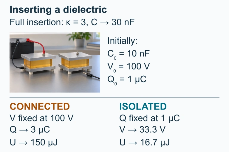 For complete insertion of a dielectric with κ = 3, capacitance triples. The connected capacitor holds voltage fixed; the isolated capacitor holds charge fixed.
SECTION 8
Connection to RC Circuits and Beyond
In AP Physics 2, capacitors appear not only as static energy-storage devices but also in RC circuits, where a resistor controls the rate at which the capacitor charges or discharges. The time constant τ = RC sets the characteristic timescale: after one time constant the capacitor has charged to about 63% of its final voltage. Although the exponential charging equation itself is treated qualitatively on the AP exam, understanding how C and R jointly govern circuit behavior is essential for experimental design and qualitative FRQs.
| Concept | Static Capacitor (This Lesson) | RC Circuit (Advanced) |
|---|---|---|
| Focus | Energy storage, field, and geometry | Time-dependent charging/discharging |
| Key equation | C = Q/ΔV ; U = ½CV² | V(t) = V₀(1 − ) |
| Math level | Algebra | Exponential functions (qualitative on AP 2) |
| AP exam relevance | MCQ and FRQ every year | Experimental design FRQs, graph interpretation |
Static capacitor concepts vs. RC circuit extensions
Beyond the AP course, capacitors connect to the concept of energy density in electromagnetic fields (u = ½ε₀E²), AC circuit impedance, and the displacement current that Maxwell added to Ampère's law. Each of these extensions builds directly on the static-capacitor foundations developed here, so a solid grasp of this material will pay dividends throughout electromagnetism.
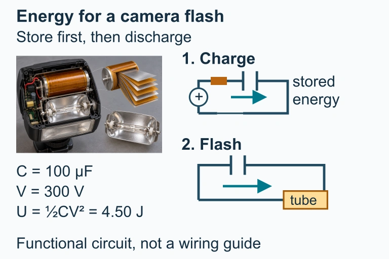 A capacitor stores energy while charging and releases energy into a flash tube on discharge; some energy may be lost.
SECTION 9
Practice Problems
Question 1: CONCEPTUAL
- A. C halves, Q unchanged, ΔV doubles
- B. C halves, Q halves, ΔV unchanged
- C. C doubles, Q unchanged, ΔV halves
- D. C halves, Q doubles, ΔV quadruples
Show answer (A)
Question 2: BASIC CALCULATION
- A. 1.9 × 10⁻⁴ J
- B. 4.2 × 10⁻⁵ J
- C. 3.8 × 10⁻⁴ J
- D. 2.1 × 10⁻² J
Show answer (A)
Question 3: INTERMEDIATE
- A. 2.0 V
- B. 4.0 V
- C. 6.0 V
- D. 12 V
Show answer (C)
Question 4: APPLIED
Show answer
Question 5: CRITICAL THINKING