

AP Physics 1 • Fluids

Fluids and Conservation Laws

How conservation of mass and energy govern the behavior of flowing fluids through Bernoulli's principle and the continuity equation.

An orbit with symbols for force and motion.
Inside this lesson 10 sections 5 questions 8 figures

SECTION 1

Historical Context & Motivation

Humans have engineered systems to control the flow of water for thousands of years—from Roman aqueducts to Persian qanats—yet the formal physics of fluid motion remained elusive until the eighteenth century. The challenge was formidable: unlike rigid bodies, fluids deform continuously under shear stress, and tracking the motion of every particle in a flowing stream seemed impossible. The breakthrough came when physicists recognized that the same conservation laws governing the mechanics of solid objects—conservation of mass and conservation of energy—could be adapted to describe flowing fluids. This realization unified hydrostatics (fluids at rest) with hydrodynamics (fluids in motion) and laid the groundwork for modern engineering applications ranging from aircraft wing design to medical blood-flow analysis.

1687 • Newton's Principia

Isaac Newton formalized the concept of viscosity and proposed that shear stress in a fluid is proportional to velocity gradient, establishing a mechanical framework later applied to fluid dynamics.

1738 • Bernoulli's Hydrodynamica

Daniel Bernoulli published Hydrodynamica, deriving the relationship between fluid speed and pressure by applying energy conservation to fluid flow—what we now call Bernoulli's principle.

1755 • Euler's Equations of Fluid Motion

Leonhard Euler derived the general differential equations of inviscid fluid flow, extending Bernoulli's work to three dimensions and providing the mathematical backbone of modern fluid mechanics.

1842 • Continuity Equation Formalized

Building on mass conservation, physicists formally stated the continuity equation for incompressible fluids, linking cross-sectional area and flow speed in pipes and channels.

1904 • Prandtl's Boundary Layer Theory

Ludwig Prandtl introduced the boundary layer concept, explaining why ideal-fluid conservation laws (Bernoulli's equation) work well far from surfaces but need correction near solid boundaries.

The central question that this lesson addresses is deceptively simple: when a fluid flows through a pipe that narrows or widens, what happens to its speed and pressure, and why? The answer emerges directly from two conservation laws you already know—conservation of mass and conservation of energy—applied to a continuous medium rather than a discrete object.

SECTION 2

Core Principles & Definitions

Before diving into the mathematics, it is essential to establish the physical assumptions and vocabulary that underpin fluid conservation laws. In AP Physics 1, we restrict our analysis to ideal fluids—fluids that are incompressible, have no viscosity (internal friction), and exhibit steady (non-turbulent) flow. These simplifications allow us to apply energy and mass conservation in clean, algebraic forms. Real fluids deviate from this ideal, but the results remain remarkably accurate for many practical situations, especially at moderate flow speeds far from solid boundaries.

1

Incompressibility

The fluid's density ρ remains constant throughout the flow. This is an excellent approximation for liquids and for gases moving well below the speed of sound.
2

Steady (Laminar) Flow

At every fixed point in space, the fluid velocity does not change with time. Streamlines—the paths traced by fluid particles—are smooth curves that never cross.
3

Non-Viscous Flow

No energy is lost to internal friction between adjacent fluid layers. This means no drag forces act within the fluid itself, so mechanical energy is conserved along a streamline.
4

Continuity (Mass Conservation)

Fluid cannot appear or disappear. The mass flowing into any section of a pipe per unit time must equal the mass flowing out, linking cross-sectional area to flow speed.
5

Bernoulli's Principle (Energy Conservation)

Along a streamline, the sum of pressure energy, kinetic energy per unit volume, and gravitational potential energy per unit volume remains constant—a direct consequence of the work-energy theorem.
✦

KEY TAKEAWAY

Think of an ideal fluid flowing through a pipe as analogous to cars on a highway with no exits or on-ramps. The number of cars passing any cross-section per minute must be the same everywhere (continuity). If the highway narrows, the cars must speed up to maintain that rate. Meanwhile, the total energy budget of each car—its kinetic energy plus its "pressure" from bumper-to-bumper traffic plus its gravitational potential energy on hills—stays fixed (Bernoulli). These two constraints, mass conservation and energy conservation, together determine every aspect of the flow.

SECTION 3

Visual Explanation — Flow Through a Converging Pipe

Converging pipe diagram showing continuity and Bernoulli's principleIdeal Fluid Flowing Through a Converging PipeSection 1A₁ (large)Section 2A₂ (small)v₁ (slow)v₂ (fast)High Pressure · Low SpeedLow Pressure · High SpeedA₁v₁ = A₂v₂ and P₁ + ½ρv₁² + ρgh₁ = P₂ + ½ρv₂² + ρgh₂
A fluid enters the wide section (Section 1) at low speed and high pressure, then accelerates through the narrow section (Section 2) where the pressure drops. The violet dashed line marks the large cross-sectional area A1, and the cyan dashed line marks the smaller area A2. The arrow lengths represent flow speed—longer arrows in the narrow section indicate faster flow. The top equation summarizes both the continuity equation and Bernoulli's equation.

The diagram above illustrates the two conservation laws acting simultaneously. As the pipe narrows, the continuity equation demands that the fluid speed increase to maintain the same volume flow rate. Since the fluid is incompressible, the same mass must pass through every cross-section per unit time, so A₁v₁ = A₂v₂. Simultaneously, Bernoulli's equation tells us that the increase in kinetic energy per unit volume must be compensated by a decrease in pressure. This inverse relationship between speed and pressure is often counterintuitive—students expect that faster-moving fluid should "push harder"—but it follows directly from energy conservation. The fluid does more kinetic work on itself as it accelerates, drawing from its internal pressure energy reservoir.

SECTION 4

Mathematical Framework

The Continuity Equation (Mass Conservation)

Consider an incompressible fluid flowing through a pipe whose cross-sectional area changes from A₁ to A₂. In a small time interval Δt, the volume of fluid entering section 1 is A₁v₁Δt, and the volume leaving section 2 is A₂v₂Δt. Because the fluid is incompressible (ρ is constant), mass conservation requires that these volumes be equal. Dividing both sides by Δt yields the equation of continuity.

EQUATION OF CONTINUITY

A1v1=A2v2A₁v₁ = A₂v₂

A = cross-sectional area (m²), v = fluid speed (m/s). The product Av is the volume flow rate Q (m³/s), which remains constant throughout the pipe.

Bernoulli's Equation (Energy Conservation)

Bernoulli's equation can be derived from the work-energy theorem applied to a fluid element moving along a streamline. The net work done on the fluid element by pressure forces equals the change in its kinetic energy plus the change in its gravitational potential energy. For an ideal fluid (non-viscous, incompressible, steady flow), this yields a powerful relationship. Each term has units of pressure (Pa = N/m² = J/m³), so Bernoulli's equation is fundamentally an energy-per-unit-volume equation.

BERNOULLI'S EQUATION

P1+½ρv12+ρgh1=P2+½ρv22+ρgh2P₁ + ½ρv₁² + ρgh₁ = P₂ + ½ρv₂² + ρgh₂

P = fluid pressure (Pa), ρ = fluid density (kg/m³), v = fluid speed (m/s), g = gravitational acceleration (9.8 m/s²), h = elevation above a reference level (m). Each term represents energy per unit volume: P is pressure energy density, ½ρv² is kinetic energy density, and ρgh is gravitational potential energy density.

Special Cases

HORIZONTAL FLOW (h₁ = h₂)

P1+½ρv12=P2+½ρv22P₁ + ½ρv₁² = P₂ + ½ρv₂²

When the pipe is level, the gravitational terms cancel. An increase in speed must be accompanied by a decrease in pressure, and vice versa.

STATIC FLUID (v₁ = v₂ = 0)

P2=P1+ρg(h1−h2)P₂ = P₁ + ρg(h₁ − h₂)

When the fluid is at rest, Bernoulli's equation reduces to the familiar hydrostatic pressure equation. Pressure increases with depth, consistent with Pascal's law.

SECTION 5

Applications and Physical Intuition

The interplay between the continuity equation and Bernoulli's equation explains a surprisingly wide range of phenomena. Understanding these applications deepens your physical intuition and prepares you for the AP Physics 1 exam, where problems often require you to translate between verbal descriptions, diagrams, and mathematical relationships.

Three applications of Bernoulli's principle: Venturi tube, airplane wing, and tank drainingThree Classic Applications of Fluid Conservation LawsVenturi TubeP highP lowP highNarrow section → fast flow → low PAirplane Wing (Lift)Fast → Low PSlow → High PΔP creates upward net force (lift)Torricelli's Theoremv=√(2gh)hFluid exits at speed √(2gh)Summary of Conservation Law ApplicationsVenturi EffectContinuity: A₁v₁ = A₂v₂ → narrow pipe = faster flowBernoulli: faster flow = lower pressureUsed in: carburetors, medical aspirators, flow metersAerodynamic LiftCurved upper surface → longer path → faster airflowLower P above wing, higher P below → net upward forceNote: real lift also involves angle of attackTorricelli's TheoremTank surface: v ≈ 0, P = P_atmHole: P = P_atm → v = √(2gh)Same speed as free fall from height h
Three canonical applications of Bernoulli's principle and the continuity equation. The Venturi tube (left) demonstrates how constriction lowers pressure. The airplane wing (center) shows how differential air speeds create lift. Torricelli's theorem (right) predicts the exit speed of fluid from a hole in a tank. Below each diagram, the relevant conservation law reasoning is summarized.

Each application in the diagram above uses both conservation laws in tandem. In the Venturi tube, continuity tells us the fluid speeds up in the constriction, and Bernoulli's equation then predicts the corresponding pressure drop. For aerodynamic lift, the asymmetric wing shape causes air to travel faster over the top surface than the bottom, creating a pressure differential that produces an upward net force. Torricelli's theorem is a special case of Bernoulli's equation where both the tank surface and the exit hole are open to the atmosphere (so the pressures cancel), and the tank is large enough that the surface velocity is approximately zero. The result—v = √(2gh)—is identical to the speed an object would reach after free-falling from height h, a beautiful connection between fluid dynamics and kinematics.
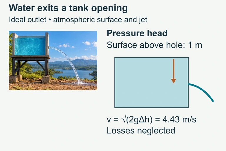
An ideal water outlet 1 m below the free surface has speed √(2gh) = 4.43 m/s. Surface and outlet are at atmospheric pressure; losses are neglected.An ideal water outlet 1 m below the free surface has speed √(2gh) = 4.43 m/s. Surface and outlet are at atmospheric pressure; losses are neglected.

Water exits a small side hole of an open elevated tank and falls toward the ground.The head driving the outlet speed is the vertical difference between the water surface and the opening. The opening’s height above the ground separately determines the jet’s flight time.
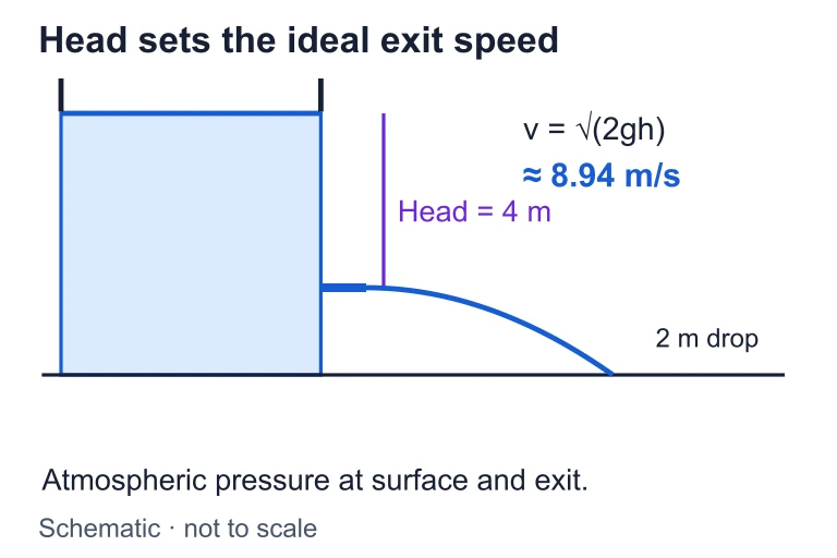
Outlet speed and jet range. With a 4 m water head and g = 10 m/s², exit speed is about 8.94 m/s. A separate 2 m drop from outlet to ground gives flight time about 0.632 s and range about 5.66 m.With a 4 m water head and g = 10 m/s², exit speed is about 8.94 m/s. A separate 2 m drop from outlet to ground gives flight time about 0.632 s and range about 5.66 m.

SECTION 6

Worked Example — Water Flowing Through a Horizontal Pipe

Water (ρ = 1000 kg/m³) flows through a horizontal pipe that narrows from a diameter of 8.0 cm to a diameter of 4.0 cm. The pressure in the wide section is 2.50 × 10⁵ Pa and the speed in the wide section is 1.5 m/s. Find: (a) the speed in the narrow section, and (b) the pressure in the narrow section.

Horizontal Pipe Flow Problem

  1. 1

    Step 1 — Identify Given Values and Target Variables

    We are given: d₁ = 8.0 cm = 0.080 m, d₂ = 4.0 cm = 0.040 m, P₁ = 2.50 × 10⁵ Pa, v₁ = 1.5 m/s, ρ = 1000 kg/m³. The pipe is horizontal, so h₁ = h₂ and the gravitational terms in Bernoulli's equation cancel. We need to find v₂ and P₂.
  2. 2

    Step 2 — Calculate Cross-Sectional Areas

    Each cross-section is circular, so A = π(d/2)² = πd²/4. Thus A₁ = π(0.080)²/4 = 5.027 × 10⁻³ m² and A₂ = π(0.040)²/4 = 1.257 × 10⁻³ m². The ratio A₁/A₂ = (d₁/d₂)² = (0.080/0.040)² = 4.
    A₁/A₂ = 4
  3. 3

    Step 3 — Apply the Continuity Equation to Find v₂

    From A₁v₁ = A₂v₂, we solve for v₂ = (A₁/A₂)v₁ = 4 × 1.5 m/s = 6.0 m/s. Halving the diameter quadruples the area ratio, which quadruples the speed—a key relationship to internalize.
    v₂ = 6.0 m/s
  4. 4

    Step 4 — Apply Bernoulli's Equation to Find P₂

    For horizontal flow: P₁ + ½ρv₁² = P₂ + ½ρv₂². Solving for P₂: P₂ = P₁ + ½ρ(v₁² − v₂²) = 2.50 × 10⁵ + ½(1000)(1.5² − 6.0²) = 2.50 × 10⁵ + 500(2.25 − 36.0) = 2.50 × 10⁵ + 500(−33.75) = 2.50 × 10⁵ − 1.6875 × 10⁴.
    P₂ ≈ 2.33 × 10⁵ Pa
  5. 5

    Step 5 — Interpret the Results

    The speed increased by a factor of 4 (from 1.5 to 6.0 m/s), while the pressure decreased by about 6.8% (from 250,000 to 233,000 Pa). This confirms Bernoulli's principle: where speed increases, pressure decreases. The pressure drop of approximately 1.69 × 10⁴ Pa equals the change in kinetic energy density ½ρΔ(v²), as energy conservation requires.
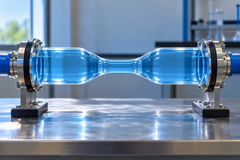
Transparent water-filled pipe with a narrow central throat and wide inlet and outlet.For steady horizontal water flow with negligible losses, narrowing the diameter from 8.0 cm to 4.0 cm raises speed from 1.5 to 6.0 m/s. With P₁ = 250 kPa, P₂ = 233.125 kPa.
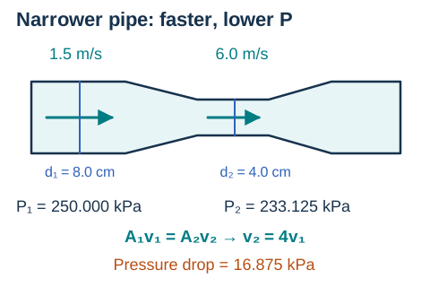
Horizontal pipe diameters 8 and 4 centimeters, speeds 1.5 and 6 meters per second, and pressures 250 and 233.125 kilopascals.For steady horizontal water flow with negligible losses, narrowing the diameter from 8.0 cm to 4.0 cm raises speed from 1.5 to 6.0 m/s. With P₁ = 250 kPa, P₂ = 233.125 kPa.Open full diagram

SECTION 7

Strengths, Limitations, and Common Misconceptions

FeatureStrengthLimitation
Continuity EquationUniversally valid for any incompressible fluid regardless of viscosity or turbulence; simple and robust.Assumes incompressibility—fails for high-speed gas flows where density changes significantly (Mach > 0.3).
Bernoulli's EquationProvides quick, accurate pressure-speed-height relationships for ideal-fluid problems; elegant energy framework.Requires non-viscous, incompressible, steady, and irrotational flow. Breaks down for turbulent flow, flow near walls, or highly viscous fluids.
Torricelli's TheoremAccurately predicts exit speed from a large tank with a small hole; connects fluid dynamics to free-fall kinematics.Assumes the tank surface area is much larger than the hole area (so v_surface ≈ 0) and neglects viscous losses at the orifice.
Ideal Fluid ModelMathematically tractable; captures essential physics for many practical scenarios with remarkable accuracy.Real fluids have viscosity. The Navier-Stokes equations (beyond AP scope) are needed for a complete description of viscous flow.

Strengths and limitations of fluid conservation laws as applied within the ideal-fluid framework

⚠

COMMON MISCONCEPTION

Many students believe that faster-moving fluid exerts more pressure on surfaces it contacts. In reality, for an ideal fluid along a streamline, faster flow corresponds to lower static pressure. The confusion arises from conflating static pressure (the pressure that acts perpendicular to the flow) with dynamic pressure or stagnation pressure. Bernoulli's equation states that static pressure plus dynamic pressure (½ρv²) is constant, so an increase in one requires a decrease in the other.
✦

KEY TAKEAWAY

Bernoulli's equation is to fluid mechanics what the work-energy theorem is to particle mechanics: it is a conservation-of-energy statement repackaged for a continuous medium. Just as the work-energy theorem lets you bypass force-by-force analysis of a sliding block, Bernoulli's equation lets you bypass the complex internal forces within a fluid and jump directly to the energetic relationships between pressure, speed, and height. The key caveat is that energy dissipation (viscosity) must be negligible for the equation to hold exactly.

SECTION 8

Connection to Advanced Fluid Mechanics

The ideal-fluid conservation laws you learn in AP Physics 1 form the foundation for much deeper and more general treatments of fluid mechanics encountered in college-level physics and engineering courses. Understanding where the AP-level treatment fits within this broader framework helps you appreciate both its power and its boundaries.

ConceptAP Physics 1 TreatmentAdvanced Treatment
Flow descriptionSteady, laminar, ideal flow along streamlinesTime-dependent, turbulent flow described by the Navier-Stokes equations (momentum conservation with viscosity)
ViscosityNeglected entirely (non-viscous approximation)Poiseuille's law describes viscous flow in pipes; boundary layers form near surfaces
CompressibilityFluid assumed incompressible (ρ = constant)Compressible flow equations used for high-speed gas dynamics; introduces Mach number and shock waves
Energy equationBernoulli's equation (mechanical energy conservation only)General energy equation including thermal energy, heat transfer, and viscous dissipation (first law of thermodynamics for fluids)
Mathematical toolsAlgebra-based equations applied between two specific pointsPartial differential equations (vector calculus), computational fluid dynamics (CFD) simulations

Comparison of AP Physics 1 fluid treatment versus advanced fluid mechanics

If you continue to study physics or engineering, you will encounter the Navier-Stokes equations, which generalize Newton's second law to viscous fluids and are among the most important—and most difficult—equations in all of physics. In fact, proving whether smooth solutions always exist for these equations is one of the unsolved Millennium Prize Problems in mathematics. Despite this complexity, the fundamental conservation principles (mass, momentum, and energy) remain the organizing framework. Everything you learn in AP Physics 1 about applying conservation laws to fluids carries forward directly into these more advanced treatments.

SECTION 9

Practice Problems

Question 1: CONCEPTUAL

Water flows steadily through a horizontal pipe that widens from a cross-sectional area of A to an area of 3A. Which of the following correctly describes the changes in fluid speed and pressure as the water moves from the narrow section to the wide section?
  • A. Speed decreases to one-third; pressure increases
  • B. Speed increases to three times; pressure increases
  • C. Speed decreases to one-third; pressure decreases
  • D. Speed remains the same; pressure increases
Show answer (A)
The correct answer is A. By the continuity equation (A₁v₁ = A₂v₂), when the area triples the speed must decrease to one-third of its original value to maintain the same volume flow rate. By Bernoulli's equation for horizontal flow (P + ½ρv² = constant), a decrease in speed means a decrease in kinetic energy density, which must be compensated by an increase in pressure. Choice B is wrong because continuity requires speed to decrease, not increase, when area increases. Choice C correctly identifies the speed change but incorrectly states that pressure decreases—this violates energy conservation. Choice D is wrong because continuity forbids constant speed when the area changes for an incompressible fluid.

Question 2: BASIC CALCULATION

Water flows through a horizontal garden hose with an inner diameter of 2.0 cm at a speed of 2.0 m/s. The hose is connected to a nozzle with an inner diameter of 0.50 cm. What is the speed of the water exiting the nozzle?
  • A. 8.0 m/s
  • B. 16 m/s
  • C. 32 m/s
  • D. 128 m/s
Show answer (C)
The correct answer is C (32 m/s). Using the continuity equation A₁v₁ = A₂v₂ with circular cross-sections, v₂ = v₁(d₁/d₂)² = 2.0 × (2.0/0.50)² = 2.0 × 16 = 32 m/s. Note that the area ratio scales as the square of the diameter ratio, not linearly. Choice A (8.0 m/s) incorrectly uses v₂ = v₁(d₁/d₂) without squaring the diameter ratio. Choice B (16 m/s) likely results from using radii instead of diameters but still forgetting the square. Choice D (128 m/s) incorrectly cubes or further inflates the ratio. The key insight is that for circular pipes, the speed ratio equals the square of the diameter ratio inverted.

Question 3: INTERMEDIATE

A large open water tank is filled to a depth of 5.0 m. A small circular hole is opened in the side of the tank at a height of 1.0 m above the bottom. Assuming the tank's cross-sectional area is much larger than the hole, what is the approximate speed of water exiting the hole? (Use g = 10 m/s².)
  • A. 4.5 m/s
  • B. 8.9 m/s
  • C. 10 m/s
  • D. 14 m/s
Show answer (B)
The correct answer is B (8.9 m/s). By Torricelli's theorem, v = √(2gh), where h is the depth of the hole below the water surface, not the height of the hole above the ground. The water surface is at 5.0 m and the hole is at 1.0 m, so h = 5.0 − 1.0 = 4.0 m. Thus v = √(2 × 10 × 4.0) = √80 ≈ 8.9 m/s. Choice A (4.5 m/s) likely uses h = 1.0 m (the height of the hole above the bottom, not the depth below the surface). Choice C (10 m/s) uses h = 5.0 m (the total depth, ignoring the hole's elevation). Choice D (14 m/s) may result from using h = 5.0 + 4.0 or another algebraic error. The critical step is correctly identifying h as the vertical distance from the water surface to the hole.

Question 4: APPLIED

5 pts
A student wants to experimentally verify the continuity equation using a horizontal pipe system with interchangeable sections of different diameters. The student has access to a constant-flow water pump, sections of PVC pipe with known inner diameters (1.0 cm, 2.0 cm, 3.0 cm, and 4.0 cm), a stopwatch, a graduated cylinder, a ruler, and a pressure gauge. (a) Describe an experimental procedure the student could use to test whether A₁v₁ = A₂v₂ holds for water flowing through pipes of different diameters. Include how the student would measure flow speed. (b) Identify an appropriate graph the student should plot and explain how the graph would confirm the continuity equation. (c) Identify one significant source of experimental error and explain whether it would cause the measured flow speeds to be higher or lower than predicted.
Show answer
Point-by-point rubric: [1 point] (a) Procedure: The student should connect each pipe diameter to the pump output one at a time while keeping the pump at the same constant setting. For each pipe, the student measures the volume flow rate Q by collecting water in the graduated cylinder over a timed interval (Q = Volume/time). The flow speed is then calculated as v = Q/A, where A = π(d/2)² is computed from the known pipe diameter. [1 point] (a) Data collection: The student should record diameter d, cross-sectional area A, collected volume V, time t, flow rate Q = V/t, and computed speed v = Q/A for each of the four pipe sections, performing multiple trials for each diameter. [1 point] (b) Graph: The student should plot flow speed v (y-axis) versus 1/A (x-axis). If the continuity equation holds, the volume flow rate Q = Av is constant, so v = Q × (1/A). The graph should be linear and pass through the origin with slope equal to Q. Alternatively, the student could plot Av (the computed flow rate) versus pipe diameter and show it is constant. [1 point] (c) Source of error identified: Viscous losses (friction) in the pipe cause the actual flow speed to be lower than the ideal prediction, especially in narrower pipes where viscous effects are more significant. The pump must work harder against friction in narrow pipes, reducing the actual flow rate Q. [1 point] (c) Direction of error explained: Because viscosity dissipates energy, the measured speeds in narrower pipes will be slightly lower than predicted by the ideal continuity equation. This means the measured Av product will not be perfectly constant but will decrease slightly for smaller-diameter pipes.

Question 5: CRITICAL THINKING

4 pts
A student observes that when they place their thumb partially over the end of a garden hose, the water sprays much farther. The student claims: "The water pressure must be increasing at the nozzle because the water goes farther." (a) Using Bernoulli's equation, explain why the student's reasoning is incorrect. (b) Provide the correct physical explanation for why the water travels farther when the opening is restricted. (c) The student then asks: "If pressure decreases where flow is fastest, how can a fire hose knock someone down with high-pressure water?" Resolve this apparent paradox.
Show answer
Point-by-point rubric: [1 point] (a) Bernoulli's equation (P + ½ρv² = constant for horizontal flow) shows that where speed increases, the static pressure within the fluid must decrease, not increase. The student's claim that pressure increases at the nozzle contradicts energy conservation. The water at the restricted opening has higher speed and therefore lower internal (static) pressure. [1 point] (b) The water travels farther because the continuity equation (A₁v₁ = A₂v₂) requires the water speed to increase dramatically when the cross-sectional area of the opening is reduced by the thumb. Since the water exits at a much higher velocity, it has greater kinetic energy and therefore travels farther as a projectile after leaving the hose. The increased range is due to increased exit speed, not increased pressure. [1 point] (c-i) The paradox is resolved by distinguishing between the static pressure within the flowing stream (which is low) and the stagnation pressure that develops when the moving fluid is brought to rest against a surface. When the fast-moving water hits a person or wall, its kinetic energy is converted back into pressure (called stagnation or dynamic pressure). The total pressure upon impact is P_static + ½ρv², which can be very large. [1 point] (c-ii) More precisely, Bernoulli's equation along a streamline that terminates at the person's body gives P_stagnation = P_stream + ½ρv². Since v is large, the stagnation pressure is large. The fire hose produces high impact force not because the water has high static pressure at the nozzle exit, but because it has high kinetic energy that converts to pressure upon being stopped.

SUMMARY

Lesson Summary

Summary

This lesson demonstrated how two fundamental conservation laws—conservation of mass and conservation of energy—govern the behavior of ideal fluids in motion. The equation of continuity (A₁v₁ = A₂v₂) ensures that an incompressible fluid speeds up when flowing through a narrower cross-section, while Bernoulli's equation (P + ½ρv² + ρgh = constant) reveals that the resulting speed increase must be accompanied by a pressure decrease. These two equations, used together, explain phenomena from the Venturi effect to aerodynamic lift to Torricelli's theorem (v = √(2gh)).

The key assumptions of the ideal fluid model—incompressibility, zero viscosity, and steady laminar flow—define the boundaries of validity for Bernoulli's equation. When these conditions are reasonably met, the equation provides a powerful shortcut for relating pressure, speed, and height at any two points along a streamline. Remember: the inverse relationship between speed and pressure is a direct consequence of energy conservation, not an arbitrary rule, and always be careful to distinguish static pressure within the flow from stagnation pressure upon impact.

Varsity Tutors • AP Physics 1: Algebra-Based • Fluids and Conservation Laws