

SECTION 1
Historical Context & Motivation
Humans have exploited geothermal energy — heat originating from within Earth — for thousands of years, initially through hot springs used for bathing and heating. Ancient Romans channeled naturally heated water into public baths and underfloor heating systems, while Māori communities in New Zealand cooked with geothermal steam long before European contact. The modern era of geothermal technology began in the early twentieth century, when engineers first converted subsurface steam into electricity, demonstrating that Earth's thermal gradient could serve as a continuous energy resource.
1904 • First Geothermal Electricity
1960 • The Geysers, California
1970s • Binary Cycle Innovation
2006 • Enhanced Geothermal Systems (EGS)
2020s • Global Expansion
The central question motivating geothermal development is straightforward: can humanity tap the enormous thermal reservoir beneath its feet reliably and sustainably, with lower greenhouse-gas emissions than fossil fuels and without the intermittency that limits solar and wind? Understanding the geophysical principles, plant designs, and environmental trade-offs of geothermal energy is essential for evaluating its role in any decarbonization strategy.
SECTION 2
Core Principles & Definitions
Geothermal energy derives from two main sources of heat inside Earth: residual heat from planetary accretion and the continuous decay of radioactive isotopes such as uranium-238, thorium-232, and potassium-40 in the mantle and crust. The geothermal gradient — the rate at which temperature increases with depth — averages roughly 25–30 °C per kilometer in continental crust, though it can exceed 100 °C/km near tectonic plate boundaries and volcanic hot spots. A viable geothermal reservoir requires three ingredients: a heat source, a permeable reservoir rock containing fluid, and an impermeable cap rock that traps the heated fluid underground.
Geothermal Gradient
Hydrothermal Reservoir
Capacity Factor
Renewable Classification
SECTION 3
Anatomy of a Geothermal System
In the diagram, the impermeable cap rock (purple band) prevents heated fluid from migrating to the surface uncontrolled. Below it, the permeable reservoir rock stores water heated by the underlying magma chamber. The production well taps into this reservoir at depths typically ranging from 1 to 3 km, while the injection well completes a closed loop that prolongs the productive life of the field. This reinjection strategy is a key reason geothermal energy is classified as renewable: fluid and heat are replenished over time, provided extraction rates remain within the reservoir's natural recharge capacity.
SECTION 4
Mathematical Framework
Although AP Environmental Science emphasizes conceptual understanding, several quantitative relationships are important for evaluating geothermal systems. The most fundamental relates the thermal energy extracted from a fluid to its temperature drop, flow rate, and specific heat capacity.
THERMAL POWER EXTRACTION
P = thermal power (W), ṁ = mass flow rate of fluid (kg/s), c = specific heat capacity of water (≈ 4,186 J/(kg·°C)), ΔT = temperature drop between extracted and reinjected fluid (°C).
SUBSURFACE TEMPERATURE ESTIMATE
T(d) = temperature at depth d (°C), T_surface = mean surface temperature (°C), G = geothermal gradient (°C/km), d = depth (km). Useful for estimating reservoir temperature before drilling.
ELECTRICAL CONVERSION EFFICIENCY
η = conversion efficiency (typically 10–23% for geothermal plants, depending on technology and temperature). Dry steam plants at high temperatures achieve the upper range; binary cycle plants at lower temperatures sit near the lower end.
SECTION 5
Types of Geothermal Power Plants
Three principal plant designs dominate commercial geothermal electricity generation, each suited to a different reservoir temperature range. Selecting the right technology depends on the thermodynamic characteristics of the subsurface resource.
In a dry steam plant, steam from the reservoir drives the turbine directly. These are the oldest and simplest systems but require rare, very high-temperature reservoirs. Flash steam plants bring high-pressure hot water to the surface, where a sudden pressure drop (flashing) converts part of it to steam. This is the most widely deployed design, accounting for roughly 60% of installed geothermal capacity worldwide. Binary cycle plants use a heat exchanger to transfer thermal energy from moderate-temperature geothermal water to a secondary working fluid with a low boiling point (e.g., isobutane or isopentane). Because the geothermal fluid never contacts the turbine, binary plants produce virtually zero direct atmospheric emissions and can exploit resources too cool for flash or dry steam technology.
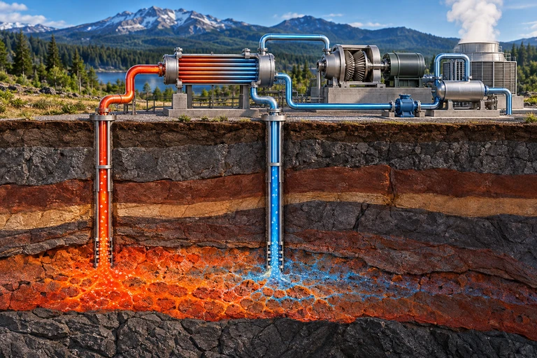 In a binary geothermal plant, brine transfers heat to a separate working fluid and is reinjected. The working fluid drives a turbine, condenses and returns through a pump. Returning fluid does not instantly replace extracted reservoir heat.
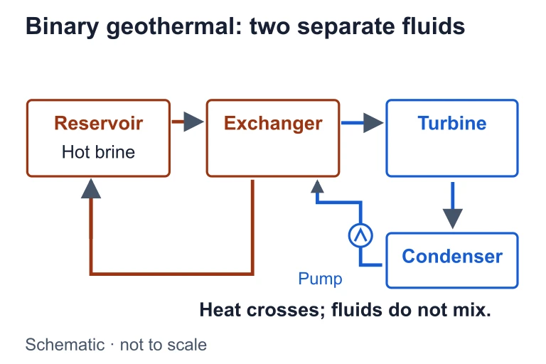 In a binary geothermal plant, brine transfers heat to a separate working fluid and is reinjected. The working fluid drives a turbine, condenses and returns through a pump. Returning fluid does not instantly replace extracted reservoir heat.
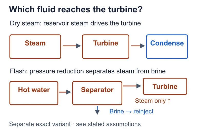 Dry-steam plants send reservoir steam to a turbine. Flash plants reduce the pressure of hot water and separate the resulting steam, while residual brine returns for reinjection.
SECTION 6
Worked Example
Worked example
- 1
Step 1 — Identify Given Values
A binary cycle geothermal plant extracts water at 150 °C and reinjects it at 70 °C. The mass flow rate is 80 kg/s. The plant's electrical conversion efficiency (η) is 12%. The specific heat capacity of water c = 4,186 J/(kg·°C). - 2
Step 2 — Calculate ΔT
ΔT = 150 °C − 70 °C = 80 °C.ΔT = 80 °C - 3
Step 3 — Calculate Thermal Power
P_thermal = ṁ × c × ΔT = 80 kg/s × 4,186 J/(kg·°C) × 80 °C = 26,790,400 W ≈ 26.79 MW.P_thermal ≈ 26.8 MW - 4
Step 4 — Apply Conversion Efficiency
P_electric = P_thermal × η = 26.8 MW × 0.12 = 3.22 MW of electrical output.P_electric ≈ 3.2 MW - 5
Step 5 — Interpret the Result
This single plant could supply roughly 3,200 average U.S. homes (assuming ~1 kW per household average demand). Despite the relatively low 12% conversion efficiency, the high capacity factor (~90%) means the plant produces power almost continuously, unlike intermittent sources.
SECTION 7
Environmental Advantages & Limitations
| Factor | Advantage | Limitation |
|---|---|---|
| CO₂ Emissions | Very low: ~45 g CO₂/kWh (binary ≈ 0); compare coal at ~1,000 g/kWh. | Flash/dry steam plants release some dissolved CO₂ and H₂S from reservoir fluids. |
| Land Use | Small footprint per MW (~1–8 acres/MW) compared to solar or wind farms. | Sites are geographically constrained to areas with adequate heat flow. |
| Reliability | Baseload power with capacity factors exceeding 90%; not weather-dependent. | Reservoir depletion can occur if extraction exceeds recharge; requires careful management. |
| Water Use | Closed-loop binary plants consume minimal freshwater. | Flash/dry steam plants may consume significant water; potential thermal pollution. |
| Induced Seismicity | Properly managed reinjection maintains reservoir pressure and stability. | EGS hydraulic fracturing can trigger minor earthquakes; public concern in some regions. |
Environmental trade-offs of geothermal energy
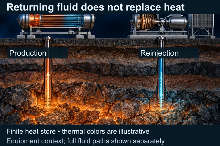 The reservoir contains a finite heat store. Returning fluid can help manage fluid supply but does not guarantee that heat replenishment matches extraction. The primary material image shows separate equipment context with schematic thermal colors. The exact companion traces a reservoir-fluid production and reinjection path on one heat-exchanger side and a distinct turbine–condenser–pump circuit on the other; only heat crosses the dividing wall. A second companion uses a common zero-based scale for explicitly synthetic final heat stores: 100 + 20 − 20 = 100 and 100 + 20 − 35 = 85.
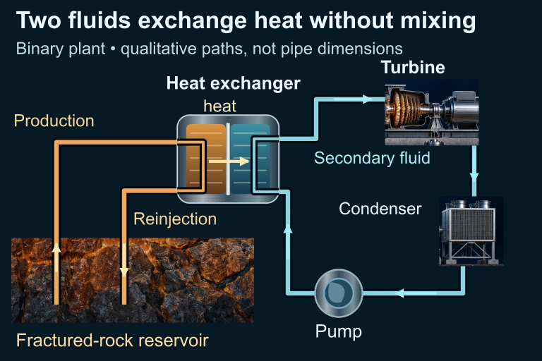 The reservoir-fluid and turbine-fluid circuits do not mix; only heat crosses the heat-exchanger wall.
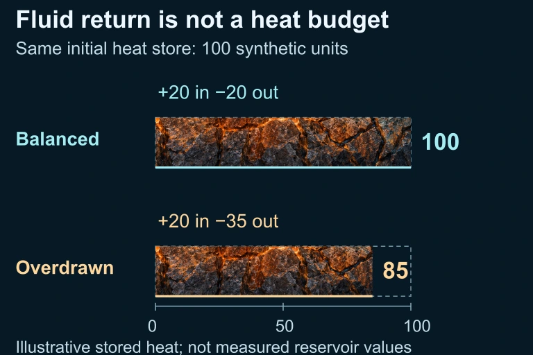 Equal initial heat stores and equal input give different final stores when extraction changes; reinjection alone does not ensure heat sustainability.
SECTION 8
Enhanced Geothermal Systems & Future Directions
Conventional geothermal technology requires naturally occurring hydrothermal reservoirs, which limits deployment to volcanically active regions such as the Pacific Ring of Fire, the East African Rift, and Iceland. Enhanced Geothermal Systems (EGS) aim to overcome this geographic constraint by engineering reservoirs in hot dry rock. The process involves drilling deep wells (3–10 km), hydraulically fracturing the rock to create permeability, and circulating injected water through the fractured zone to extract heat. If commercially scaled, EGS could theoretically make geothermal energy accessible nearly anywhere on the planet, since temperatures suitable for power generation exist at sufficient depth beneath most continental surfaces.
| Feature | Conventional Hydrothermal | Enhanced Geothermal (EGS) |
|---|---|---|
| Reservoir | Natural: hot water/steam trapped in permeable rock | Engineered: hydraulic fracturing creates permeability in hot dry rock |
| Geographic Availability | Limited to tectonically active areas | Potentially global — heat exists at depth everywhere |
| Drilling Depth | 1–3 km typical | 3–10 km, significantly increasing cost |
| Key Risk | Reservoir depletion if over-extracted | Induced seismicity from fracturing; high upfront capital cost |
| Maturity | Commercially proven since 1960s | Pilot and demonstration phase; active R&D |
Conventional vs. Enhanced Geothermal Systems
Looking ahead, advances in deep drilling technology (including millimeter-wave and plasma drilling), improved subsurface imaging, and lessons from the oil and gas industry's experience with hydraulic fracturing are converging to reduce EGS costs. Several countries have invested in pilot projects — including the Soultz-sous-Forêts project in France and the Frontier Observatory for Research in Geothermal Energy (FORGE) site in Utah. If EGS achieves cost-competitiveness, geothermal could transition from a niche contributor to a major pillar of global decarbonized energy systems.
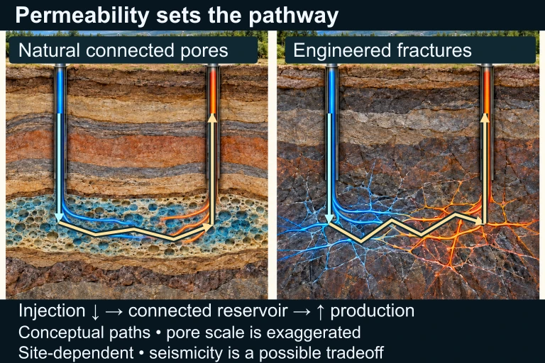 Conventional hydrothermal resources have naturally connected fluid-bearing permeability. Enhanced geothermal systems engineer connected fractures in suitable hot rock. Downward injection, connected reservoir paths and upward production are authored on the preserved geological cutaways. These are conceptual paths, not actual pore scale or a detailed surface power cycle; resource performance and possible induced seismicity depend on site conditions.
SECTION 9
Practice Problems
Question 1: CONCEPTUAL
- A. Geothermal plants produce zero carbon dioxide emissions under all operating conditions.
- B. Earth's internal heat is continuously generated by radioactive decay and residual accretion energy, replenishing reservoirs on human timescales when properly managed.
- C. Geothermal reservoirs contain infinite supplies of hot water that never require reinjection.
- D. Geothermal energy can only be harvested in volcanic regions, ensuring natural replenishment through eruptions.
Show answer (B)
Question 2: BASIC CALCULATION
- A. 100 °C
- B. 115 °C
- C. 75 °C
- D. 150 °C
Show answer (B)
Question 3: INTERMEDIATE
- A. 4.1 MW
- B. 23.0 MW
- C. 41.5 MW
- D. 0.41 MW
Show answer (A)
Question 4: APPLIED
Show answer
Question 5: CRITICAL THINKING