
SECTION 1
Historical Context & Motivation
The concept of fault tolerance emerged from a deeply practical concern: how can a system continue operating correctly even when some of its components fail? In the early days of computing, single points of failure could bring entire organizations to a halt, and as computer networks became critical infrastructure for military, academic, and commercial purposes, the need for resilient, self-healing designs became a matter of national security and economic survival. The history of fault tolerance is inseparable from the history of the internet itself, where the guiding architectural principle was that no single destroyed node or severed cable should be able to take down the entire communication network.
1964 • Paul Baran's Distributed Networks
1969 • ARPANET Goes Online
1983 • TCP/IP Standardized
2006 • Cloud Computing & Redundancy at Scale
This history reveals a recurring theme: as networks become more important, the cost of failure increases, and designers respond by adding redundancy — extra connections, backup routes, and duplicate components that ensure data can still flow when parts of the system go down. The central question that fault tolerance answers is deceptively simple: how many connections must exist in a network so that removing any single one does not disconnect the remaining nodes?
SECTION 2
Core Principles & Definitions
At its core, fault tolerance is the ability of a system — especially a computer network — to continue providing service even when one or more of its components (nodes, connections, or devices) fail. A fault-tolerant system does not prevent faults from occurring; rather, it is designed so that faults do not cascade into complete system failures. Understanding fault tolerance requires a firm grasp of several foundational ideas that the AP CSP framework emphasizes.
Redundancy
Single Point of Failure
Routing Flexibility
Graceful Degradation
KEY TAKEAWAY
SECTION 3
Visual Explanation — Network Topologies & Fault Tolerance
The degree of fault tolerance a network possesses depends heavily on its topology — the arrangement of nodes and connections. The diagram below contrasts three common topologies to illustrate how redundancy affects resilience. In a linear topology, removing a single connection can split the network in two. A tree or star topology centralizes traffic through a hub, creating a dangerous single point of failure. A mesh topology, by contrast, provides multiple independent paths between every pair of nodes, making it highly fault tolerant.
The diagram above makes a critical point for the AP exam: adding redundant connections between nodes increases fault tolerance but also increases cost and complexity. In a full mesh network with n nodes, every node connects directly to every other node, yielding n(n − 1) / 2 connections. The internet itself is not a full mesh, but its core backbone routers use a partial mesh with enough redundancy to survive the failure of multiple links simultaneously.
SECTION 4
How Fault Tolerance Works — Mechanisms & Protocols
Fault tolerance in computer networks is achieved through a combination of physical redundancy (extra cables, routers, and servers) and logical mechanisms embedded in networking protocols. When a packet travels from a source to a destination, it may pass through dozens of intermediate routers, and at each hop the routing protocol selects the best available path. If a link goes down, routing tables are updated, and subsequent packets are automatically rerouted. This process is largely invisible to end users, which is precisely the goal.
Connections in a Full Mesh
FULL MESH CONNECTIONS
Where C is the total number of direct connections and n is the number of nodes. This formula counts every unique pair of nodes. A full mesh of 4 nodes requires 4 × 3 / 2 = 6 connections; a full mesh of 10 nodes requires 45. The quadratic growth explains why full meshes are impractical for large networks.
Minimum Connections for Fault Tolerance
MINIMUM FAULT-TOLERANT CONNECTIONS
For a network of n nodes to tolerate the failure of any single connection without disconnecting any node, every node must have a degree of at least 2 (i.e., at least two connections). A minimal 2-connected network can be arranged as a ring, requiring exactly n connections.
Beyond physical redundancy, the internet relies on several key protocols and strategies. Packet switching breaks data into small packets that can each take independent paths through the network, so a failure on one path only affects some packets, which can be retransmitted. Dynamic routing protocols such as BGP (Border Gateway Protocol) and OSPF (Open Shortest Path First) continuously monitor link status and recalculate optimal paths. Data replication stores copies of important data across multiple servers or data centers so that if one server crashes, the data remains accessible from another location.
SECTION 5
Topology Analysis — Identifying Redundancy & Failures
A common AP CSP exam question presents a network diagram and asks you to identify which connection(s) could fail without disrupting communication between two specific nodes, or conversely, which single failure would disconnect part of the network. Answering these questions requires systematically tracing paths. The diagram below shows a six-node network with both redundant and non-redundant connections, along with annotations highlighting the critical analytical approach.
AP EXAM TIP
SECTION 6
Worked Example — Evaluating a Network for Fault Tolerance
Consider a network of five devices (P, Q, R, S, T) with the following connections: P–Q, P–R, Q–R, Q–S, R–S, S–T. We want to determine whether the network is fault tolerant with respect to every pair of devices — specifically, can every device still communicate with every other device if any single connection fails?
Fault Tolerance Analysis of a Five-Node Network
- 1
Step 1 — Draw the Network and Count Connections
The network has 5 nodes and 6 connections. A fully connected (full mesh) network of 5 nodes would have 5 × 4 / 2 = 10 connections, so this is a partial mesh. List the degree (number of connections) of each node: P has degree 2 (connects to Q, R), Q has degree 3 (P, R, S), R has degree 3 (P, Q, S), S has degree 3 (Q, R, T), and T has degree 1 (only S).Node T has degree 1 — an immediate red flag for fault tolerance. - 2
Step 2 — Identify Potential Single Points of Failure
Because node T has only one connection (S–T), the link S–T is a critical link. If S–T fails, there is no alternative path to reach T from any other node. This means the network is not fully fault tolerant — at least one single connection failure can disconnect part of the network.Connection S–T is a critical link (bridge). - 3
Step 3 — Verify Redundancy for the Remaining Nodes
Now consider just nodes P, Q, R, S. Remove any single connection and check connectivity. Remove P–Q: P can still reach Q via P→R→Q (or P→R→S→Q). Remove P–R: P→Q→R still works. Remove Q–R: Q→P→R or Q→S→R. Remove Q–S: Q→R→S. Remove R–S: R→Q→S. In every case, the four nodes remain connected.The subnetwork {P, Q, R, S} IS fault tolerant for single connection failures. - 4
Step 4 — Propose a Fix
To make the entire network fault tolerant, node T needs at least one additional connection to a node other than S. Adding a T–R connection, for example, would mean that if S–T fails, T can still communicate via T→R, and if T–R fails, T can still communicate via T→S. Now every node has degree ≥ 2, and no single connection failure disconnects the network.Adding connection T–R makes the network fault tolerant (7 connections total).
 Cables and equipment carry data between devices. To test fault tolerance, identify the logical links and check which routes remain after a specified failure.
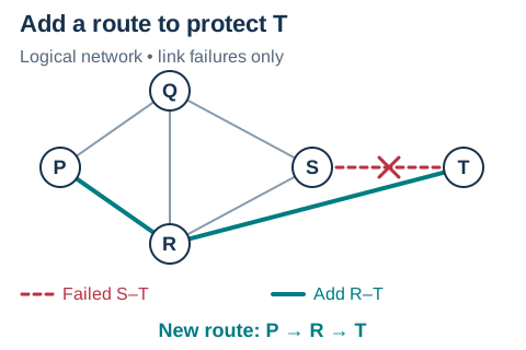 In the original graph, S–T is T’s only connection. Add R–T: when S–T fails, the route P → R → T survives. This test keeps every device operational and changes one link.Open full diagram
SECTION 7
Tradeoffs — Cost, Complexity, and Performance
Fault tolerance does not come for free. Every redundant connection requires physical infrastructure (cables, routers, switches), ongoing maintenance, and increases the complexity of routing decisions. Network designers must balance the level of redundancy against practical constraints such as budget, geography, and management overhead. The table below summarizes the key tradeoffs involved in increasing a network's fault tolerance.
| Factor | Benefit of More Redundancy | Cost of More Redundancy |
|---|---|---|
| Reliability | Network stays connected despite multiple failures | More hardware to monitor and maintain |
| Performance | Alternative paths can reduce congestion by distributing traffic | Routing tables grow, increasing processing time for each hop |
| Financial Cost | Prevents costly downtime (e.g., lost revenue from outages) | Full mesh connections grow quadratically: n(n − 1)/2 |
| Scalability | New nodes can be added with built-in backup paths | Each new node in a full mesh requires connections to all existing nodes |
Tradeoffs in network fault tolerance design
KEY TAKEAWAY
SECTION 8
Fault Tolerance Beyond Networks — Distributed Systems & the Cloud
While the AP CSP curriculum focuses primarily on network-level fault tolerance (redundant connections between devices), the same principles extend to every layer of modern computing. Cloud computing platforms like AWS, Google Cloud, and Microsoft Azure implement fault tolerance at the levels of individual servers, data centers, and entire geographic regions. Understanding these broader applications helps contextualize why fault tolerance is one of the defining design principles of the modern internet.
| Level of Fault Tolerance | AP CSP Scope | Advanced / Cloud Scope |
|---|---|---|
| Connection Level | Redundant cables and links between routers; packets rerouted around failures | Software-defined networking (SDN) can instantly reconfigure virtual links |
| Device Level | A failed router is bypassed via alternative paths | Server clusters with automatic failover; load balancers distribute requests |
| Data Level | Conceptual — data reaches destination via alternative route | Data replicated across multiple data centers; RAID storage arrays |
| Geographic Level | Not explicitly tested but implied by internet's global structure | Multi-region deployments survive natural disasters affecting entire data centers |
Fault tolerance: AP CSP scope vs. advanced applications
For the AP exam, remember that the core idea remains the same at every level: redundancy enables a system to continue operating when components fail. Whether the redundancy exists in extra network cables, duplicate servers, or geographically distributed data centers, the principle is identical. The internet was specifically designed with this principle as a foundational requirement, and understanding fault tolerance helps explain why the internet has proven remarkably resilient over decades of explosive growth.
SECTION 9
Practice Problems
Question 1: CONCEPTUAL
- A. The network is fault tolerant because every device can communicate with every other device.
- B. The network is fault tolerant because there are four separate connections, providing redundancy.
- C. The network is not fault tolerant because the central device is a single point of failure; if it fails, no outer device can communicate with any other.
- D. The network is not fault tolerant because star topologies cannot use packet switching.
Show answer (C)
Question 2: BASIC CALCULATION
- A. 16
- B. 28
- C. 56
- D. 64
Show answer (B)
Question 3: INTERMEDIATE
- A. The connection X–Z is a single point of failure because Z has only one connection.
- B. If connection W–X fails, device W can no longer communicate with device X.
- C. The subnetwork consisting of W, X, and Y is fault tolerant for single connection failures.
- D. Adding a connection Y–Z would eliminate all single points of failure in the network.
Show answer (A,C,D)
Question 4: APPLIED
3 ptsShow answer
Question 5: CRITICAL THINKING
4 ptsShow answer
SUMMARY
Fault Tolerance — Summary
Summary
Fault tolerance is the ability of a system to continue functioning when individual components fail, and it is achieved primarily through redundancy — providing multiple independent paths between network nodes. A single point of failure is any component whose failure alone would disconnect part of the network. Networks designed as mesh topologies are more fault tolerant than linear or star topologies because they offer multiple alternative routes for data. A full mesh of n nodes requires n × (n − 1) / 2 connections, which grows quadratically — making full meshes impractical for large networks.
The internet uses a partial mesh design combined with dynamic routing protocols and packet switching to reroute traffic around failed links automatically. When analyzing a network diagram for fault tolerance, trace all possible paths between two nodes; if removing any single connection still leaves at least one viable path between every pair of nodes, the network is fault tolerant for single failures. The key tradeoff is that more redundancy improves reliability but increases cost, complexity, and maintenance requirements — a central theme in the design of robust computing systems.